Lenovo ThinkPad X30 ThinkPad X30, X31, X32 - Hardware Maintenance Manual - Page 97
pulling
 |
View all Lenovo ThinkPad X30 manuals
Add to My Manuals
Save this manual to your list of manuals |
Page 97 highlights
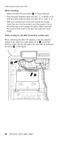
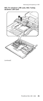
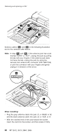
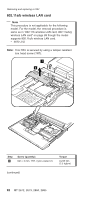
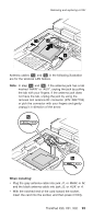
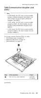
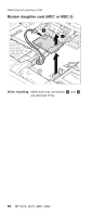
Removing and replacing a FRU 3 4 3 Antenna cables 5a and 5b in the following illustration are for the wireless LAN feature. Note: In step 5a and 5b , if the antenna jack has a tab marked "MAIN" or "AUX", unplug the jack by pulling the tab with your fingers. If the antenna jack does not have the tab, unplug the jack by using the removal tool antenna RF connector (P/N: 08K7159) or pick the connector with your fingers and gently unplug it in direction of the arrow. 5a 5b When installing: v Plug the gray antenna cable into jack J1, or MAIN, or M, and the black antenna cable into jack J2, or AUX, or A. v With the notched end of the card toward the socket, insert the card into the socket, and then press it firmly. ThinkPad X30, X31, X32 93
-
 1
1 -
2
-
3
-
4
-
5
-
6
-
7
-
8
-
9
-
10
-
11
-
12
-
13
-
14
-
15
-
16
-
17
-
18
-
19
-
20
-
21
-
22
-
23
-
24
-
25
-
26
-
27
-
28
-
29
-
30
-
31
-
32
-
33
-
34
-
35
-
36
-
37
-
38
-
39
-
40
-
41
-
42
-
43
-
44
-
45
-
46
-
47
-
48
-
49
-
50
-
51
-
52
-
53
-
54
-
55
-
56
-
57
-
58
-
59
-
60
-
61
-
62
-
63
-
64
-
65
-
66
-
67
-
68
-
69
-
70
-
71
-
72
-
73
-
74
-
75
-
76
-
77
-
78
-
79
-
80
-
81
-
82
-
83
-
84
-
85
-
86
-
87
-
88
-
89
-
90
-
91
-
 92
92 -
 93
93 -
 94
94 -
 95
95 -
 96
96 -
 97
97 -
 98
98 -
 99
99 -
 100
100 -
 101
101 -
 102
102 -
103
-
104
-
105
-
106
-
107
-
108
-
109
-
110
-
111
-
112
-
113
-
114
-
115
-
116
-
117
-
118
-
119
-
120
-
121
-
122
-
123
-
124
-
125
-
126
-
127
-
128
-
129
-
130
-
131
-
132
-
133
-
134
-
135
-
136
-
137
-
138
-
139
-
140
-
141
-
142
-
143
-
144
-
145
-
146
-
147
-
148
-
149
-
150
-
151
-
152
-
153
-
154
-
155
-
156
-
157
-
158
-
159
-
160
-
161
-
162
-
163
-
164
-
165
-
166
-
167
-
168
-
169
-
170
-
171
-
172
-
173
-
174
-
175
-
176
-
177
-
178
-
179
-
180
-
181
-
182
-
183
-
184
-
185
-
186
-
187
-
188
-
189
-
190
-
191
-
192
-
193
-
194
-
195
-
196
 |
 |

4
3
3
Antenna
cables
±5a²
and
±5b²
in
the
following
illustration
are
for
the
wireless
LAN
feature.
Note:
In
step
±5a²
and
±5b²
,
if
the
antenna
jack
has
a
tab
marked
“MAIN”
or
“AUX”,
unplug
the
jack
by
pulling
the
tab
with
your
fingers.
If
the
antenna
jack
does
not
have
the
tab,
unplug
the
jack
by
using
the
removal
tool
antenna
RF
connector
(P/N:
08K7159)
or
pick
the
connector
with
your
fingers
and
gently
unplug
it
in
direction
of
the
arrow.
5b
5a
When
installing:
v
Plug
the
gray
antenna
cable
into
jack
J1
,
or
MAIN
,
or
M
,
and
the
black
antenna
cable
into
jack
J2
,
or
AUX
,
or
A
.
v
With
the
notched
end
of
the
card
toward
the
socket,
insert
the
card
into
the
socket,
and
then
press
it
firmly.
Removing
and
replacing
a
FRU
ThinkPad
X30,
X31,
X32
93