Lexmark M410 Service Manual
Lexmark M410 - Optra B/W Laser Printer Manual
 |
UPC - 734646261005
View all Lexmark M410 manuals
Add to My Manuals
Save this manual to your list of manuals |
Lexmark M410 manual content summary:
- Lexmark M410 | Service Manual - Page 1
Lexmark OptraTM M410/M412 4045-XXX • Table of Contents • Start Diagnostics • Safety and Notices • Trademarks • Index • Manuals Menu Lexmark and Lexmark with diamond design are trademarks of Lexmark International, Inc., registered in the United States and/or other countries. - Lexmark M410 | Service Manual - Page 2
you supply in any way it believes appropriate without incurring any obligation to you. You can purchase additional copies of publications related to this product by calling 1-800-553-9727. In other countries, contact your point of purchase. Lexmark and Optra are trademarks of Lexmark International - Lexmark M410 | Service Manual - Page 3
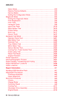
Contents Notices and Safety Information vii Laser Notices vii Safety Information xv General Information 1-1 Options 1-2 Printer Specifications 1-3 Diagnostic Information 2-1 Start 2-1 Service Error Codes 2-2 User Status Messages 2-5 User Error Messages 2-9 Power-On Self Test (POST 2-14 - Lexmark M410 | Service Manual - Page 4
3-29 Repair Information 4-1 Handling ESD-Sensitive Parts 4-1 Adjustment Procedures 4-2 Printhead Assembly 4-2 Paper Alignment 4-3 Removal Procedures 4-4 Covers 4-4 Charge Roller 4-8 Controller Board 4-9 Cooling Fan 4-11 Developer Drive Assembly 4-13 Engine Board 4-14 iv Service Manual - Lexmark M410 | Service Manual - Page 5
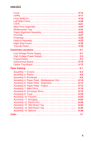
4-30 Transfer Roller 4-30 Connector Locations 5-1 Low Voltage Power Supply 5-1 High Voltage Power Supply 5-2 Engine Board 5-4 Interconnect Board 5-10 Option Tray Board 5-12 Parts Catalog 6-1 Assembly 1: Covers 6-2 Assembly 2: Frame 6-6 Assembly 3: Printhead 6-8 Assembly 4: Paper Feed - Lexmark M410 | Service Manual - Page 6
4045-XXX vi Service Manual - Lexmark M410 | Service Manual - Page 7
4045-XXX Notices and Safety Information Laser Notices The following laser notice labels may be affixed to this printer as shown: Laser Advisory Label Notices and Safety Information vii - Lexmark M410 | Service Manual - Page 8
4045-XXX Class 1 Laser Statement Label viii Service Manual - Lexmark M410 | Service Manual - Page 9
in the wavelength region of 770-795 nanometers. The laser system and printer are designed so there is never any human access to laser radiation above a Class I level during normal operation, user maintenance, or prescribed service condition. Laser Der Drucker erfüllt gemäß amtlicher Bestätigung der - Lexmark M410 | Service Manual - Page 10
della potenza di 5mW che opera sulla lunghezza d'onda compresa tra 770 e 795 nanometri. Il sistema laser e la stampante sono stati progettati in modo tale che le persone a contatto con la stampante, durante verse afectada por ningún tipo de radiación láser superior al nivel de x Service Manual - Lexmark M410 | Service Manual - Page 11
CFR Subchapter J, voor andere landen in IEC 825. Laserprodukten van klasse I worden niet als ongevaarlijk aangemerkt. De printer is voorzien van een laser van klasse IIIb (3b), dat wil zeggen een gallium arsenide-laser van 5 milliwatt met een golflengte van 770-795 nanometer. Het lasergedeelte en de - Lexmark M410 | Service Manual - Page 12
Klasse IIIB (3b)-laser, der nominelt er en 5 milliwatt galliumarsenid laser, som arbejder på ohitettaessa olet alttiina näkymättömälle lasersäteilylle. Älä katso säteeseen. VARNING! och spärren är urkopplad. Betrakta ej strålen. Laser-notis Denna skrivare är i USA certifierad att motsvara kraven - Lexmark M410 | Service Manual - Page 13
utsätts för laserstrålning över Klass I-nivå vid normal användning, underhåll som utförs av användaren eller annan föreskriven serviceåtgärd. Laser-melding Skriveren er godkjent i USA etter kravene i DHHS 21 CFR, underkapittel J, for klasse I (1) laserprodukter, og er i andre land godkjent som et - Lexmark M410 | Service Manual - Page 14
4045-XXX Japanese Laser Notice Chinese Laser Notice xiv Service Manual - Lexmark M410 | Service Manual - Page 15
with the use of specific Lexmark components. The safety features of some parts may not always be obvious. Lexmark is not responsible for the use of other replacement parts. • The maintenance information for this product has been prepared for use by a professional service person and is not intended - Lexmark M410 | Service Manual - Page 16
videntes. Lexmark ne peut être tenu responsable de l'utilisation d'autres pièces de rechange. • Les consignes d'entretien et de réparation de ce produit s'adressent uniquement à un personnel de maintenance qualifi elektrischen Schlags und körperlicher Verletzung. Das zuständige xvi Service Manual - Lexmark M410 | Service Manual - Page 17
aprobado para cumplir los más estrictos estándares de seguridad global usando los componentes específicos de Lexmark. Puede que las características de seguridad de algunas piezas no sean siempre evidentes. Lexmark no se hace responsable del uso de otras piezas de recambio. • La información sobre el - Lexmark M410 | Service Manual - Page 18
la utililització de components específics de Lexmark. Les característiques de seguretat d'algunes peces pot ser que no sempre siguin òbvies. Lexmark no es responsabilitza de l'us d'altres peces El personal professional ha d'estar-ne assabentat i prendre les mesures convenients. xviii Service Manual - Lexmark M410 | Service Manual - Page 19
4045-XXX Chinese Safety Information Korean Safety Information Notices and Safety Information xix - Lexmark M410 | Service Manual - Page 20
4045-XXX xx Service Manual - Lexmark M410 | Service Manual - Page 21
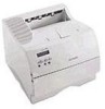
4045-XXX 1. General Information The Lexmark OptraTM M410 and M412 laser printers are letterquality laser page printers designed to attach to an IBM compatible Personal Computer and to most computer networks. The M410 printer is capable of printing at speeds of 12 pages per minute. The M412 is - Lexmark M410 | Service Manual - Page 22
following options are available. Some options are not available in every country. Contact your point of purchase for options available in your country. 500-Sheet Drawer SDRAM Memory DIMMs: 4MB, 8MB, 16MB, 32MB for SCS External Network Adapter: Marknet Pro 1 and 3 series compatible 1-2 Service Manual - Lexmark M410 | Service Manual - Page 23
4045-XXX Printer Specifications Acoustics Operating: - Lexmark M410 | Service Manual - Page 24
4045-XXX Maintenance Approach The diagnostic information in this manual leads you to the correct field replaceable unit (FRU) or part. Use the service error codes, user status messages, user error messages, service checks, and diagnostic aids to determine the printer problem and repair the failure. - Lexmark M410 | Service Manual - Page 25
EPROM ESD FRU GB HVPS LASER LCD LED LVPS MROM Supply Masked Read Only Memory Nonvolatile Random Access Memory Original Equipment Manufacturer Photoconductor Power-On Reset Power-On Self Test Raster Imaging Processor Read Only Memory Single In-Line Memory Module Static Random Access Memory Used Parts - Lexmark M410 | Service Manual - Page 26
4045-XXX 1-6 Service Manual - Lexmark M410 | Service Manual - Page 27
Power Saver is invoked, and then Power Saver is displayed. If a user status message is displayed, go to the "User Status Messages" on page 2-5. User error messages are indicated by a two or three-digit error code that provides the user with information that explains a problem with a print cartridge - Lexmark M410 | Service Manual - Page 28
hot during printing or when printer is idle. Go to the "Hot Fuser Service Check" on page 2-25. 924 Fuser Error An open circuit has been detected in the Fuser Thermistor Circuit. Go to the "Hot Fuser Service Check" on page 2-25. 931-935 Printhead Error These errors represent a problem with the - Lexmark M410 | Service Manual - Page 29
If no problem is found, replace the FRUs in the following order: controller board engine board interconnect board 941 Controller Code CRC 941 960 RAM Memory Error Note: The controller software also can cause a 939 error code. Contact your next level for software support. Replace the controller - Lexmark M410 | Service Manual - Page 30
into the code overlay SIMM. The specific error is as follows: 964 - Download Emulation CRC Failure. Checksum Failure. 965 - Download Emulation Outdated, The Download Emulation and the controller code are incompatible. Go to "Download Emulation" on page 3-3. The following errors indicate a failure - Lexmark M410 | Service Manual - Page 31
the second line of the display. Press Select to Reset the printer. The printer is busy receiving or processing data, or printing data. Note: The printer indicator light blinks while the printer is processing data. Press Stop to take the printer out of Busy. The Not Ready message is displayed. No - Lexmark M410 | Service Manual - Page 32
menus because Print Menu Settings is selected from the menu. Press Stop to take the printer out of Ready. The Not Ready message is displayed. No more data is processed, but the printer processes all paper currently in the printer paper path. Press Go to return to Ready after the page prints. Press - Lexmark M410 | Service Manual - Page 33
Resetting Printer Formatting Flash (Do Not Power Off) Program Flash (Do Not Power Off) Formatting Disk Status Action The printer is Reset Printer is on the second line of the display. Press Select to reset the printer. The printer is deleting any print jobs in process and restoring all settings - Lexmark M410 | Service Manual - Page 34
XXX User Status Message Programming Disk (Do Not Power Off) Menus Disabled Activating Menu Changes Status this message is displayed. The printer is reset to No button actions are activate a printer setting possible while this changed in the menus. message is displayed. 2-8 Service Manual - Lexmark M410 | Service Manual - Page 35
This message displays when the printer's front door is open or the print cartridge is missing. If this message cannot be cleared go to "Cover Open Switch/Cable Service Check" on page 2-19. 34 Short Paper The printer determines the paper length is too short to print the formatted data. This occurs - Lexmark M410 | Service Manual - Page 36
4045-XXX User Error Message Explanation 39 Complex Page This message is displayed when the page is too complex to print. 51 Defective Flash This message is displayed when the printer detects a defective flash. This error may occur at power on, or during flash format and write operations. Press - Lexmark M410 | Service Manual - Page 37
to the disk. This message displays for both resource and PostScript Disk operators when the disk is full. This error code displays when the printer detects an unformatted disk at power on. Press Go to clear the message. The disk is marked as bad and normal operation continues. Disk operations - Lexmark M410 | Service Manual - Page 38
LocalTalk Infrared USB Fax The printer configuration ID is not set or is invalid. This condition can only be cleared when a valid configuration ID is set. Go to "Setting Configuration ID" on page 3-15. This is the host interface from which the printer is currently drawing data. 2-12 Service Manual - Lexmark M410 | Service Manual - Page 39
it. When the option is recognized, the printer automatically clears the error and continues. If the option is experiencing a hardware problem, turn the printer off and back on. If the error occurs again, turn the printer off, remove the option and call for service. Diagnostic Information 2-13 - Lexmark M410 | Service Manual - Page 40
on. The fuser takes longer to warm up from a cold start than a warm start. 7. The cooling fan turns on and runs full speed. 8. The main drive motor turns on. 9. The developer drive assembly drives the developer shaft in the toner cartridge. 10. The exit rollers turn. 11. The printhead mirror motor - Lexmark M410 | Service Manual - Page 41
feed problems - Base printer or Integrated 250 Paper Tray Paper jams at exit of Redrive Assembly. Print quality - Black page Print quality - Blank page Print quality - Light print Print quality - Background Print quality - Residual image Print quality - Skew Print quality - Banding Print quality - Lexmark M410 | Service Manual - Page 42
of copy. Paper feed problem with 500 sheet paper tray option. Action Go to "Print Quality - Toner on backside of printed page" on page 2-47. Go to "Print Quality - Black bands on outer edges of the page" on page 2-44. Go to "Input Tray(s) Option Service Check" on page 2-26. 2-16 Service Manual - Lexmark M410 | Service Manual - Page 43
. • Paper feed Problems with error message: Use the "User Error Messages" on page 2-9 to help diagnose the problem. • Print Quality Problems: Go to "Print Quality Test Pages" on page 3-2 and print a test page to help diagnose problems before changing any settings or working on the printer. • Use the - Lexmark M410 | Service Manual - Page 44
and Bushing Action Check the right side charge roll arm and bushing for correct assembly operation. Check the right charge roll bushing for signs of wear or contamination. . If incorrect, replace the right charge roller arm. Note: The screw that attaches the charge roll lead to the contact must be secure - Lexmark M410 | Service Manual - Page 45
4045-XXX Cover Open Switch/Cable Service Check FRU 1 Toner Cartridge 2 Cover Open Switch/Cable Assembly Action Check the toner cartridge to make sure it is correctly installed and that the right and left cartridge tracks are not loose or broken. Check to make sure the cover open switch activation - Lexmark M410 | Service Manual - Page 46
Check Note: Remove any paper handling options before servicing the printer for a dead machine condition. Observe all necessary ESD precautions when removing and handling the controller board, engine board or any of the installed option cards or assemblies. Service Tip: The LVPS uses a self-docking - Lexmark M410 | Service Manual - Page 47
blow after LVPS installed in the printer. 8 LVPS 9 Engine Board power. Measure the voltages on LVPS output connector CN1. If any voltages are incorrect, replace the LVPS. Turn the printer , turn the printer off and reconnect one cable at a time until you find the defective assembly. Service Tip: A - Lexmark M410 | Service Manual - Page 48
Lamp Service Check Error code 928 may be displayed when the printer detects that the erase lamp assembly, cable or engine board is defective. Note: If the erase lamp assembly is defective, both the erase lamp and lens are replaced as a kit. Make the following checks when a 928 service error displays - Lexmark M410 | Service Manual - Page 49
the engine board. Fuser Service Check Cold Fuser Service Check Error codes 920, 921, and 922 may display for a cold fuser failure. A 920 error caused by low line voltage can sometimes be cleared by turning the machine off and then on again. Service Tip: Set the Fuser Temperature to NORMAL before - Lexmark M410 | Service Manual - Page 50
at the fuser assembly. Turn the printer on and check across the cable for line voltage. If incorrect, remove the LVPS and check both F1 and F2 fuses. Remove the LVPS from the printer. Replace any open fuses and attach the power cord. If the fuses open, replace the LVPS. If the fuses open after the - Lexmark M410 | Service Manual - Page 51
toner, label glue, labels or other contaminants. If any are found, repair as necessary or replace the fuser assembly. Input Sensor Service Check Service Tip: Run the Base Sensor Test. Check the input sensor for proper operation. The display changes from open to closed as the sensor flag is manually - Lexmark M410 | Service Manual - Page 52
the continuity of the input sensor cable. If incorrect, replace the cable. If correct, replace the input sensor assembly. Input Tray(s) Option Service Check 500-Sheet Input Tray Option Service Tip: Try all the other input paper sources to make sure they are properly feeding paper. Run the Tray - Lexmark M410 | Service Manual - Page 53
cable on the base printer. Replace the cable if the contacts are defective. Printer displays message "Insert Tray 1" when trying to print from Tray 2 message displays when tray 2 has paper in the tray. FRU 1 Paper Path/Guides/Tray 2 2 Pick Roll 3 Solenoid Action Check the paper path for any - Lexmark M410 | Service Manual - Page 54
4045-XXX FRU 4 Tray 2 Motor Action Use the Tray 2 Motor Test to check the tray 2 motor. Replace as necessary. 2-28 Service Manual - Lexmark M410 | Service Manual - Page 55
the toner cartridge removed, inform the customer to replace the toner cartridge. Determine if the noise is in the main drive assembly, fuser, developer drive assembly or alignment assembly. Look for any loose, worn or binding parts in all assemblies. Repair as necessary. If a service error code 936 - Lexmark M410 | Service Manual - Page 56
no gear error code 936 or assembly engine board Operator Panel Service Check Operator Panel Buttons Service Check Note: Before continuing with this service check do the "Button Test" on page 3-9 and "Operator Panel Test" on page 3-21. FRU 1 Operator Panel Assembly assembly. 2-30 Service Manual - Lexmark M410 | Service Manual - Page 57
4045-XXX Operator Panel Display Service Check SERVICE TIP: The printer has detected a problem with the engine board, operator panel cable or operator panel assembly if POST does not complete and the printer emits 5 beeps and stops in a continuous pattern until the printer is turned off. The operator - Lexmark M410 | Service Manual - Page 58
the test fails, replace the FLASH DIMM. If the problem continues, replace the controller board. DRAM Memory Option(s) This service check is the same as the flash memory option service check with the following exception: Run the "DRAM Memory Test" on page 3-9 from the menu if the DRAM Memory DIMM is - Lexmark M410 | Service Manual - Page 59
installed in the socket on the interconnect board and is properly grounded. If you find no problem, contact your next level of support before replacing the network card. Error Code 54 - Network Card A 54 error displays when the RIP software detects that a network card is installed in slot 1 on the - Lexmark M410 | Service Manual - Page 60
Printer continually feeds paper. FRU 1 Pick Roll Solenoid 2 Pick Roll Shaft Assembly roller shaft assembly to make sure the solenoid actuator correctly interlocks with the cam. Replace the pick roll shaft assembly manner. If the problem persists, it may there is still a problem. Failures occur mainly - Lexmark M410 | Service Manual - Page 61
roll or slick spots. If you find a problem, replace the pick roll assembly. Check to ensure the media that is being fed through the multipurpose tray assembly meets recommended paper specifications. Parallel Port Service Check Run the "Parallel Wrap Test" on page 3-10. Note: The Parallel Wrap Test - Lexmark M410 | Service Manual - Page 62
4045-XXX Printhead Service Check The printhead assembly does not contain any service replaceable parts or components. Service Error Code 1 Error Code 931 No first HYSNC Signal Error Code 932 Lost HYSNC 2 Error Code 935 Mirror Motor unable to reach operating speed Explanation These errors usually - Lexmark M410 | Service Manual - Page 63
be checked at different resolution settings). • Print Darkness: Set to NORMAL. • Toner Saver: Set to OFF. • PQET: Set to OFF. An incorrect printer driver for the installed software can cause problems. Incorrect characters could print and the copy may not fit the page correctly. Measure all voltages - Lexmark M410 | Service Manual - Page 64
4045-XXX Print Quality - All Black Page Service Tip: An all black page is generally caused by a problem in the high voltage system or an incorrect high voltage in the printing process resulting in toner development on the entire photoconductor drum. FRU 1 High Voltage Contacts 2 Engine Board 3 HVPS - Lexmark M410 | Service Manual - Page 65
continuity, replace the HVPS. Generally a 93x service error is posted if the printhead assembly fails and the printer does not give a blank copy symptom. The printhead used in the printer does not have a mechanical shutter as previous laser printers. The printer is interlocked through the front top - Lexmark M410 | Service Manual - Page 66
Quality - Blurred or Fuzzy Print Blurred or fuzzy print is usually caused by a problem in the main drive gearbox assembly, alignment assembly, any feed roller or in the transfer roll bearings or transfer roll. Check the gearbox assembly for correct operation. Check the transfer roll for binds or - Lexmark M410 | Service Manual - Page 67
15.6 mm (0.61 inch) apart Replace the FRUs in the following order: developer drive assembly 4 Lines spaced 47 mm (1.85 inch) apart main drive assembly Replace the FRUs in the following order: toner cartridge charge roll 5 Lines spaced 38.0 mm (1.50 inches) apart Lines spaced 46.5 mm (1.83 - Lexmark M410 | Service Manual - Page 68
assembly. Print Quality - Background Service Tip: Some background problems can be caused by rough papers or non-Lexmark toner cartridges. If the rough paper mode is on, turn it off and run the print test. Some slick or coated papers may also cause background. Some problems occur with printers - Lexmark M410 | Service Manual - Page 69
the lens and lamp assembly. Check the erase lamp assembly. Use the same procedure as outlined in the "Erase Lamp Test" on page 3-26. The printhead on the Optra M410 printers cannot be cleaned. Try another printhead if all other attempts fail to correct a background problem. Check the high voltage - Lexmark M410 | Service Manual - Page 70
fixes or changes the problem, then check the springs and charge roll link arm assemblies for binds or defective parts. Replace as necessary. Check the charge roll for any signs of toner buildup or other contamination on the outer edges that correspond to the bands on the page. Check the charge links - Lexmark M410 | Service Manual - Page 71
. If correct, replace the engine board. Print Quality - Residual Image Service Tip: Install a new print cartridge if available before doing this service check. Residual image can be caused by the photoconductor, cleaning blade and other parts inside the print cartridge. Diagnostic Information 2-45 - Lexmark M410 | Service Manual - Page 72
FRU 1 Erase Lamp Assembly 2 Fuser Assembly Print Quality - Light Print Action Check the erase lamp lens assembly for any signs of paper dust, toner buildup or any other contamination. Clean with a soft cloth or replace the lens and lamp assembly which are provided together in a kit. If the lens - Lexmark M410 | Service Manual - Page 73
Toner on backside of printed page Service Tip: This is generally caused by loose toner in the machine in the paper path being carried through the printer on the backside of the paper. FRU 1 Fuser Assembly 2 Transfer Roll Action Toner is being carried out on the backside of the media. This problem - Lexmark M410 | Service Manual - Page 74
52 mm. Any print quality problems such as lines that are spaced 52 mm apart indicate you should check the transfer roll for damage, toner or foreign material buildup. CAUTION: Make sure the printer is powered Off before making any checks on the transfer roll or associated parts for personal safety - Lexmark M410 | Service Manual - Page 75
printer failures and verify repairs have corrected the problem. To run the printer diagnostic tests described in this chapter, you must put the printer in Diagnostic Mode. Configuration Mode Configuration Mode contains a set of menus, settings Press the Select button to open sub menu options. 7. - Lexmark M410 | Service Manual - Page 76
from the CONFIG MENU. The following is printed on page 1. • Margin Settings • Contents of the Diagnostic Error Log. • Printer configuration information: - printer serial number, controller code level, engine code level, operator panel code level, smart option code levels, font versions, and so on - Lexmark M410 | Service Manual - Page 77
jobs. To discard all buffered jobs: 1. Select Buffered Jobs from the CONFIG MENU. 2. Select Disable. Download Emulation To help resolve Download Emulation problems, the following steps are necessary to instruct the printer to POR without activating any download emulations. Diagnostic Aids 3-3 - Lexmark M410 | Service Manual - Page 78
printer is idle, a new Emulator can be downloaded again. Note: If the user power cycles the printer after selecting the Disable option, the Downloaded Emulator will be reactivated. Demo Mode The Demo Mode setting the factory default values occurs upon exiting of the CONFIG MENU. 3-4 Service Manual - Lexmark M410 | Service Manual - Page 79
4045-XXX Narrow Media The Narrow Media selection is used to set media width. To change media width: 1. Select Narrow operator panel in the order shown: • Print Registration • Print Tests • Hardware Tests • Input Tray Tests • Base Sensor Test • Printer Setup • Error Log • Device Tests (if installed) - Lexmark M410 | Service Manual - Page 80
Margin: -10 to +10 To set Print Registration: 1. Select Registration from the Page completes printing, the Registration screen displays again. The "Quick Test Page" should be printed on letter or A4 paper. Print Tests The purpose of the diagnostic Print Tests is to verify that the printer can print - Lexmark M410 | Service Manual - Page 81
to assist in Print Quality and Paper Feed problems. Print Quality Test Pages The purpose of this diagnostic function is to allow printing of the print quality test pages with the toner cartridge lockout function disabled. The print quality test consists of three pages. Page one contains a mixture - Lexmark M410 | Service Manual - Page 82
Error Log. • Printer configuration information: - printer serial number, controller code level, engine code level, operator panel code level, smart option code levels, font versions, and so on. • Values for the Quality Menu settings used to print the pages. Printing Menu Settings Page Service Manual - Lexmark M410 | Service Manual - Page 83
menu. - With no buttons pressed, several OP (Open) appear on the display. 2. Press each button one set and read correctly. To run the DRAM Memory Test: 1. Select DRAM Memory Test from the menu. - The power memory test has failed and finished with errors. Initially 00000 displays with the maximum fail - Lexmark M410 | Service Manual - Page 84
seconds: ROM Checksum Error ROM Burst Read Error Once the maximum pass count or fail count is reached, the test stops with the power indicator on solid. Test from the menu. - The power indicator blinks indicating the test is in progress. The test runs continuously until canceled. 3-10 Service Manual - Lexmark M410 | Service Manual - Page 85
DMA Memory Error DMA Background Error Clear Init Rise Error False Init Rise Error Autofeed Rising Interrupt Error Clear Autofeed Rise Error False Autofeed Rise Error Autofeed Falling Interrupt Error Clear Autofeed Fall Error Once the maximum count is reached the test stops. The power indicator goes - Lexmark M410 | Service Manual - Page 86
Data 232 Error Data 422 Error FIFO Error DSR Error DSR PIO Error DSR Interrupt Error CTS Error CTS PIO Error CTS Interrupt Error Once the maximum count is reached the test stops. The power indicator goes on solid and the final results display. Press Return/Stop to exit the test. 3-12 Service Manual - Lexmark M410 | Service Manual - Page 87
printer. A blank sheet of paper feeds through the printer as the laser turns off during this test. The only way to observe the paper path is to open IN = Input Tray Inserted Sensor 2. Once this message displays, you can manually actuate each sensor. The tray empty sensor can be actuated by hand, - Lexmark M410 | Service Manual - Page 88
Base Sensor Test. - The operator panel displays OP for open and CL for closed. 2. Manually toggle the sensors by hand to verify that each sensor switches from open to closed. Printer Setup Setting the Page Count This lets you change the page count from the Diagnostic menu. This is used whenever the - Lexmark M410 | Service Manual - Page 89
Configuration ID is on a label located inside the printer. The label is visible when the top front cover is open. - The leftmost digit blinks indicating that it is and the printer automatically PORs to activate the new setting. Note: When the printer PORs it does so in the normal mode. Diagnostic - Lexmark M410 | Service Manual - Page 90
is visible when you open the upper front cover. Edge To Edge When Edge To Edge is set to "On", the printer's graphics and printing engine shift all four margins (top, bottom, right and left) to the physical edges of the page. When Edge To Edge is set to "Off", the printing area is set back to the - Lexmark M410 | Service Manual - Page 91
is helpful by providing a history of printer errors. The error log contains the 12 most recent errors that have occurred on the printer. The most recent error displays in position 1 and the oldest error displays in position 12 (if 12 errors have occurred). If an error occurs after the log is full - Lexmark M410 | Service Manual - Page 92
screen updates periodically indicating the percentage of test completed and the number of bad blocks found. 3. The power indicator blinks during the test. The test can be canceled anytime during the test by pressing Return/Stop Go or Return/Stop to return to the Device Tests menu. 3-18 Service Manual - Lexmark M410 | Service Manual - Page 93
because the flash is reformatted at the end of the test. To run the Flash Test: 1. Select Flash Test from the Device Tests menu. - The power indicator blinks while the test is running. - "Flash Test/Test Passed" message displays if the test passes and the - Lexmark M410 | Service Manual - Page 94
the Operator Panel Test again once you scroll past it. You can scroll forward and backward through the other tests without powering the printer off and on. Service Tip: If "Engine Service" appears on the operator panel once the printer is turned on, one of the operator panel buttons is stuck. 3-20 - Lexmark M410 | Service Manual - Page 95
4045-XXX Operator Panel Test Use the Operator Panel Test to diagnose both the operator panel display and buttons. To run the Operator Panel Test: 1. Press GO to initiate Operator Panel Test. 2. Press the buttons in the order shown in the following table and check the results on the display. If you - Lexmark M410 | Service Manual - Page 96
This causes all gears in the printer to turn. Remove the print cartridge before performing this test to prevent toner from spilling into the printer. The MPF and Tray 1 pick roller solenoids can be actuated from the properly, check the cable connections leading to the solenoid. 3-22 Service Manual - Lexmark M410 | Service Manual - Page 97
. Once the Tray 2 motor is turned on, select the Tray 2 solenoid from the Solenoid Test to cause the pick roller to turn. Mirror Motor Test This test lets you turn on the printhead mirror motor. To run the Mirror Motor Test: 1. Select Mirror Motor from the menu. 2. Press GO to turn the - Lexmark M410 | Service Manual - Page 98
o = No paper is present. 1 = Paper is present O = Cover is open and/or cartridge is missing. C = Cover is closed and cartridge is present. O = Rear door is open. C = Rear door is closed. o = Tray 2 is not (correctly) attached to printer. 1 = Tray 2 is attached to printer. 3-24 Service Manual - Lexmark M410 | Service Manual - Page 99
thermistor value corresponding to either standby or printing fuser temperatures, depending on whether the cooling fan is set to slow or fast. The number comparison with each other to assure the fuser temperature control system is working properly. Note: The message "Error!! 00 10 24" displays if the - Lexmark M410 | Service Manual - Page 100
the LEDs turn on, they are visible with the front cover open and the cartridge removed. To run the Erase Lamp Test: 1. Select Erase Lamp code. To view the code, select Engine Firmware from the menu. The engine code version level displays on the second line of the operator panel. 3-26 Service Manual - Lexmark M410 | Service Manual - Page 101
. The second step consists of Feeding, Transferring and Fusing. Electrophotographic Process The photoconductive drum, located within the toner cartridge assembly, creates the image to be printed on a page. As the PC drum makes a full rotation, it is electrically charged, an image is exposed to the - Lexmark M410 | Service Manual - Page 102
4045-XXX Paper Path/Sensor Locations 3-28 Service Manual - Lexmark M410 | Service Manual - Page 103
4045-XXX Cable Locations Diagnostic Aids 3-29 - Lexmark M410 | Service Manual - Page 104
4045-XXX 3-30 Service Manual - Lexmark M410 | Service Manual - Page 105
to electrostatic discharge (ESD). To prevent damage to ESD-sensitive parts, follow the instructions below in addition to all the usual precautions, such as turning off power before removing logic boards: • Keep the ESD-sensitive part in its original shipping container (a special "ESD bag") until you - Lexmark M410 | Service Manual - Page 106
the menu. The test page should only be printed on letter or A4 paper from Tray 1. The Print Test page consists of horizontal lines that can be used for skew adjustment, page count setting, printer serial number code levels and print registration settings. 5. Check the Print Test page for any sign of - Lexmark M410 | Service Manual - Page 107
is removed or replaced. An incorrectly adjusted alignment assembly produces vertically skewed images down the page. To perform the paper alignment adjustment: 1. Print the Print Test page and check the margin registration adjustments on the test page. These adjustments should be within the range - Lexmark M410 | Service Manual - Page 108
4045-XXX Removal Procedures CAUTION: Be sure to unplug the power cord whenever you are working on the printer with one of the covers removed. Also remove the print cartridge before you perform removal procedures. Covers Left Side Cover 1. Open the upper door and multipurpose tray. 2. Press the two - Lexmark M410 | Service Manual - Page 109
4045-XXX Right Side Cover 1. Open the upper door and multipurpose tray. 2. Remove the screw (A) located in the front of the right side frame mounted into the cover. Repair Information 4-5 - Lexmark M410 | Service Manual - Page 110
4045-XXX 3. Remove the screw (B) located at the top rear of the printer. 4. Lift the right side cover up and away from the printer. 4-6 Service Manual - Lexmark M410 | Service Manual - Page 111
4045-XXX Top Cover 1. Remove the left and right side covers. 2. Remove the two screws (A) from the right side of the top cover. 3. Remove the screw (B) from the left side of the top cover. 4. Remove the fuser air duct from the top cover. 5. Lift the top cover from the printer. Repair Information 4-7 - Lexmark M410 | Service Manual - Page 112
4045-XXX Charge Roller 1. Open the upper door and mulitpurpose tray. 2. Spread the charge roller support arms (A) apart and remove the charge roller. Note: Make sure the HVPS charge wire is pinched between the bearing and right charge roller arm, ensuring good electrical contact. 4-8 Service Manual - Lexmark M410 | Service Manual - Page 113
4045-XXX Controller Board 1. Remove the left side cover. 2. Loosen the six screws (A) and remove the outer EMC shield. Repair Information 4-9 - Lexmark M410 | Service Manual - Page 114
4045-XXX 3. Remove the four screws (B) and two screws (C) securing the inner EMC shield. 4. Lift the inner EMC shield/controller board assembly up and away from the interconnect board. 5. Remove the screws (D) from the controller board. 6. Remove the controller board from the inner EMC shield. 4-10 - Lexmark M410 | Service Manual - Page 115
4045-XXX Cooling Fan 1. Remove the top cover. 2. Remove the controller board/inner EMC shield assembly. 3. Disconnect the cooling fan from the engine board. 4. Release the two retaining tabs and push the air duct inward approximately 10 mm to provide clearance - Lexmark M410 | Service Manual - Page 116
4045-XXX 5. Remove the cooling fan. 4-12 Service Manual - Lexmark M410 | Service Manual - Page 117
Remove the two screws (A) and screw (B). 3. Remove the developer drive assembly. Note: When you reinstall the developer drive assembly, be sure that the developer drive assembly engages with left charge roller arm. Be sure that the developer drive assembly wheel aligns with the hub on the main drive - Lexmark M410 | Service Manual - Page 118
4045-XXX Engine Board 1. Remove the inner EMC shield/controller board assembly. 2. Disconnect all connectors from the engine board. 3. Remove the four screws (A) from the engine board. 4. Lift the engine board from the interconnect board and remove the engine board. 4-14 Service Manual - Lexmark M410 | Service Manual - Page 119
4045-XXX Fuser 1. Remove the right side cover. 2. Disconnect the two LVPS wires (A) from the fuser. 3. Remove the redrive assembly. 4. Remove the screw from the inner air duct cover and remove the cover. Repair Information 4-15 - Lexmark M410 | Service Manual - Page 120
4045-XXX 5. Disconnect the thermistor from the printhead/mirror motor cable. 6. Remove the four fuser mounting screws (B) and slide the fuser out of the printer. 4-16 Service Manual - Lexmark M410 | Service Manual - Page 121
4045-XXX HVPS 1. Remove the inner deflector. 2. Disconnect the HVPS transfer wire from the HVPS (A). 3. Disconnect the HVPS cable from the HVPS (B). 4. Remove the two screws (C) securing the HVPS and remove the HVPS. Note: Make sure HVPS contacts (D) make good electrical contact with the HVPS. - Lexmark M410 | Service Manual - Page 122
4045-XXX Inner Deflector 1. Open the upper door and multipurpose tray. 2. Remove the screw (A) securing the upper paper deflector and remove the upper paper deflector. 4-18 Service Manual - Lexmark M410 | Service Manual - Page 123
4045-XXX 3. Disconnect the MPF paper sensor, remove the four screws (B) securing the MPF and remove the MPF. Repair Information 4-19 - Lexmark M410 | Service Manual - Page 124
1. Remove the redrive assembly. 2. Remove the paper alignment assembly. 3. Remove the main drive assembly. 4. Remove the rear drive assembly. 5. Remove the end stop and end stop spring from the left hinge. 6. Remove the six screws from the left side frame and remove the frame. 4-20 Service Manual - Lexmark M410 | Service Manual - Page 125
4045-XXX LVPS 1. Remove the right side cover. 2. Disconnect the fuser lamp wires from the fuser. 3. Remove the screw (A) from the bottom of the printer. Repair Information 4-21 - Lexmark M410 | Service Manual - Page 126
screw covers and remove the two screws (B) from the rear of the printer. 5. Slide the LVPS to the right and remove the LVPS. Note: When you reinstall the LVPS, connect the black fuser lamp wire to the rear contact that is labeled black and the other wire to the front contact. 4-22 Service Manual - Lexmark M410 | Service Manual - Page 127
the gear cover. 4. Remove the pick roll solenoid from the main drive assembly. 5. Remove the link (A) from the rear of the main drive assembly. 6. Remove screws (B) securing the main drive assembly. 7. Remove the main drive assembly. Note: Close the front door when you reconnect the link to the - Lexmark M410 | Service Manual - Page 128
Tray 1. Open the multipurpose tray to a position that allows the left and right tray hinge slots (A) to align with the rectangular mounting posts (B). 2. Pull upward on each tray hinge to remove the tray from the two mounting posts. Be careful not to break the hinges. 4-24 Service Manual - Lexmark M410 | Service Manual - Page 129
4045-XXX Paper Alignment Assembly 1. Remove the inner deflector. 2. Remove the pick roll. 3. Remove the paper input sensor. 4. Remove the two screws (A) from the paper alignment assembly located inside the printer. Repair Information 4-25 - Lexmark M410 | Service Manual - Page 130
from the left side frame. 7. Slide the paper alignment assembly to the right and remove it from the printer. Note: Go to the "Adjustment Procedures" on page 4-2 and perform the paper alignment adjustment whenever the paper alignment assembly is removed or the screws are loosened. 4-26 Service Manual - Lexmark M410 | Service Manual - Page 131
4045-XXX Pick Roll 1. Remove tray 1. 2. Gain access to the pick roll by positioning the printer on its right side. 3. Pull the pick roll from the pick roll shaft in the direction of the arrow (A) and remove the pick roll. Repair Information 4-27 - Lexmark M410 | Service Manual - Page 132
the printhead assembly. 3. Remove the three printhead mounting screws (A) and remove the printhead. Note: Go to the "Adjustment Procedures" on page 4-2 and perform the printhead assembly adjustment whenever the printhead is removed or the printhead mounting screws are loosened. 4-28 Service Manual - Lexmark M410 | Service Manual - Page 133
the two lower mounting screws (A). 3. Open the rear door and remove the two upper mounting screws (B). 4. Lift the redrive assembly up and away from the rear of the printer. 5. Disconnect the cables from the exit and rear door open sensors and remove the redrive assembly. Repair Information 4-29 - Lexmark M410 | Service Manual - Page 134
and remove the right side frame from the printer. Transfer Roller 1. Open the upper door and multipurpose tray. 2. Remove the print cartridge. 3. Unsnap the transfer roller from the left arm. 4. Slide the transfer roller to the left, removing the roller from the right bearing. 4-30 Service Manual - Lexmark M410 | Service Manual - Page 135
4045-XXX 5. Connector Locations Low Voltage Power Supply Connector CN1 Interconnect Board Pin No. 1 2 3 4 5 6 7 8 9 10 11 12 13 14 Signal +5 V dc +5 V dc Ground +24 V dc +24 V dc Ground N/A +5 V dc Ground Ground +24 V dc Ground Ground Heat On Connector Locations 5-1 - Lexmark M410 | Service Manual - Page 136
4045-XXX High Voltage Power Supply Connector CN1 Engine Board Pin No. 1 2 3 4 5 6 7 8 9 Signal Transfer Servo Transfer Current PWM Transfer V-Level Enable Transfer V-Level PWM Charge Enable Developer Enable Developer PWM +24 V dc Ground 5-2 Service Manual - Lexmark M410 | Service Manual - Page 137
4045-XXX Connector Locations 5-3 - Lexmark M410 | Service Manual - Page 138
Ground FPIRQPaper Input Sensor Ground LED Drive +24 V dc CVSW +24 V dc CVSW Ground Ground MMotor Clock MMotor Enable MMotor CW+ MMotor Lock +5 V dc Ground 5-4 Service Manual - Lexmark M410 | Service Manual - Page 139
-XXX Connector Pin No. J4 Cover Open Switch 1 2 3 4 5 6 7 8 J5 Printhead 1 2 3 4 5 6 7 J6 RS232C Interface X J7 Paper Output Sensor 1 Exit Tray O/C Sensor 2 3 4 5 6 Signal Not Used Not Used Not Used Not Used Not Used +5 V dc Cover Open Switch Ground Adjust LD Enable Video - Lexmark M410 | Service Manual - Page 140
4045-XXX Connector J8 Printhead (Mirror Motor) Fuser Temp Sensor J9 HVPS Pin No. 1 2 3 4 5 6 7 1 2 3 4 5 6 7 8 9 Signal PMotor Clock PMotor Lock PMotor Enable Ground +24 V Transfer V-Level PWM Transfer V-Level PWM Charge Enable Developer Enable Developer PWM +24 V CVSW Ground 5-6 Service Manual - Lexmark M410 | Service Manual - Page 141
4045-XXX Connector Pin No. J10 Option (Integrated) 1 Paper Tray 2 3 4 5 6 7 8 9 10 11 12 J11 MMF/D-Roll 1 2 3 4 J12 Erase Lamp 1 2 J13 Fan Motor 1 2 J14 X J15 Interconnect Board N/A J16 X Signal Tray1 Present Sensor N/A Tray2 Paper Sensor N/A Tray2 Present Sensor N/A + - Lexmark M410 | Service Manual - Page 142
4045-XXX Connector J17 MMF Input Sensor Pin No. 1 2 3 Signal MMF Paper Input Sensor Ground +5 V dc 5-8 Service Manual - Lexmark M410 | Service Manual - Page 143
4045-XXX Connector Locations 5-9 - Lexmark M410 | Service Manual - Page 144
11 12 13 14 1 X Signal N/A N/A +5 V dc +5 V dc +5 V dc Ground Ground Ground +24 V dc +24 V dc +24 V dc Ground Ground Ground N.C. Heat On N/A Not Used 5-10 Service Manual - Lexmark M410 | Service Manual - Page 145
4045-XXX Connector Locations 5-11 - Lexmark M410 | Service Manual - Page 146
2 Present Sensor N/A +24 V dc CVSW T2M1ON T2M2ON N/A Ground Tray 1 Present Sensor Ground LED Drive Not Used Motor ON Ground +24 V dc CVSW Solenoid ON 5-12 Service Manual - Lexmark M410 | Service Manual - Page 147
4045-XXX Connector Locations 5-13 - Lexmark M410 | Service Manual - Page 148
4045-XXX 5-14 Service Manual - Lexmark M410 | Service Manual - Page 149
. The indenture indicates the relationship of a part to the next higher assembly. For example: INDENTURE RELATIONSHIP OF PARTS (No dot) MAIN ASSEMBLY (One dot) o Detail parts of a main assembly (One dot) o Subassembly of the main assembly (Two dot) o o Detail part of a one-dot subassembly (Two dot - Lexmark M410 | Service Manual - Page 150
4045-XXX Assembly 1: Covers 6-2 Service Manual - Lexmark M410 | Service Manual - Page 151
Fuser Cooling Air Support, Paper Bail Assembly M410 Cover, Upper Front M412 Screw w/washer, M3x8 PP12G0445 Hook, Upper Spring, Upper Hook Spring, MPF Latch Tray, MPF Input Latch, MPF Tray Cover, MPF Latch Panel Asm, Operator, 110V Panel Asm, Operator, 220V Hinge, Left Cable Asm, Op Panel & Cover Open - Lexmark M410 | Service Manual - Page 152
4045-XXX Assembly 1: Covers (continued) 6-4 Service Manual - Lexmark M410 | Service Manual - Page 153
4045-XXX AsmIndex 1-28 1-29 1-30 1-31 1-32 NS Part Number 12G0268 12G0425 12G0437 12G0438 12G0439 12G3701 Units 1 1 1 1 1 1 NS 12G3702 1 NS 12G3703 1 Description , Swedish, Finnish Overlay XNLS pack: Czech, Hungarian, Polish, Russian, Turkish Overlay pack: French/Canadian Parts Catalog 6-5 - Lexmark M410 | Service Manual - Page 154
4045-XXX Assembly 2: Frame 6-6 Service Manual - Lexmark M410 | Service Manual - Page 155
Contact, HVPS Drum Spring, Cartridge Locate Pin, Cartridge Locate Foot, Rubber Support, Cartridge Spring, IC Locate Arm, Right Arm, IC Locate, Right Sensor, Paper Input LED Asm, Erase Guide, Middle Paper Brush, Erase Guide, Paper Lever, Input Sensor Guide, Front Paper Arm, IC Locate, Left Spring - Lexmark M410 | Service Manual - Page 156
4045-XXX Assembly 3: Printhead 6-8 Service Manual - Lexmark M410 | Service Manual - Page 157
4045-XXX AsmIndex 3-1 3-2 3-3 3-3 Part Number 12G0298 12G3551 Units 3 2 1 1 Description Screw, M4x12 PP 12G0445 Washer, PP 12G0445 Printhead, Complete M410 Printhead, Complete M412 Parts Catalog 6-9 - Lexmark M410 | Service Manual - Page 158
4045-XXX Assembly 4: Paper Feed - Multipurpose Unit 6-10 Service Manual - Lexmark M410 | Service Manual - Page 159
4045-XXX AsmIndex 4-1 4-2 4-3 4-4 4-5 4-6 4-7 4-8 4-9 4-10 Part Number 12G0299 12G0301 12G0252 12G0251 12G0300 12G0302 Units 1 4 1 1 1 1 1 1 1 1 Description Roller Asm, MPF Pick Screw, M4x12 PP 12G0445 Feeder Asm, MPF Sensor, MPF Input Solenoid, MPF Pick Roller Screw, M3x8 PP 12G0445 Shaft Asm, - Lexmark M410 | Service Manual - Page 160
4045-XXX Assembly 5: Paper Feed - Alignment 6-12 Service Manual - Lexmark M410 | Service Manual - Page 161
4045-XXX AsmIndex 5-1 5-2 5-3 5-4 5-5 Part Number 12G0303 12G0452 Units 1 2 1 1 1 Description Aligner Asm, Paper Feed Screw, M4x8 PP 12G0445 Spring Washer, PP 12G0445 Screw, Adjustment M3x16 PP 12G0445 Spacer, Adjustment Screw Parts Catalog 6-13 - Lexmark M410 | Service Manual - Page 162
4045-XXX Assembly 6: Paper Feed - Output 6-14 Service Manual - Lexmark M410 | Service Manual - Page 163
12G0252 12G0307 Units 1 2 1 1 1 1 1 1 1 1 2 Description Roller, Lower Redrive Screw, M3x6 PP 12G0445 Bail, Rear Door Paper Sensor, Rear Door Deflector, Paper Door, Rear Frame, Rear Paper Exit Belt, Redrive Roller Sensor, Paper Exit Roller, Upper Redrive Screw, M4x8 PP 12G0445 Parts Catalog 6-15 - Lexmark M410 | Service Manual - Page 164
4045-XXX Assembly 7: Main Drive 6-16 Service Manual - Lexmark M410 | Service Manual - Page 165
Units 3 1 1 1 1 1 1 1 1 2 1 Description Screw, M4x12 PP 12G0445 Drive Asm, Main M410 Drive Asm, Main M412 Roller, Pick Shaft Asm, Pick Roller Clutch Spring, Pick Roller Screw, M3x8 PP 12G0445 Solenoid, Main Pick Roller Coupling, Spline Drive Washer, PP12G0445 Clip, PP12G0445 Parts Catalog 6-17 - Lexmark M410 | Service Manual - Page 166
4045-XXX Assembly 8: Developer Drive 6-18 Service Manual - Lexmark M410 | Service Manual - Page 167
4045-XXX AsmIndex 8-1 8-2 8-3 Part Number 12G0325 Units 1 1 2 Description Drive Asm, Developer Screw, M3x25 PP12G0445 Screw, M4x12 PP12G0445 Parts Catalog 6-19 - Lexmark M410 | Service Manual - Page 168
4045-XXX Assembly 9: Fuser 6-20 Service Manual - Lexmark M410 | Service Manual - Page 169
, Fuser Lamp, Rear Guide, Fuser Paper Exit Spring, Exit Sensor Lever Lever, Paper Exit Sensor Lamp, 115V M410 Lamp, 220V M410 Lamp, 115V M412 Lamp, 220V M412 Frame, Right Fuser Bushing, Hot Roll Clip, Gear Retaining Stand, Bushing Spring Spring, Roller Bushing M410 Spring, Roller Bushing M412 Parts - Lexmark M410 | Service Manual - Page 170
4045-XXX Assembly 9: Fuser (continued) 6-22 Service Manual - Lexmark M410 | Service Manual - Page 171
9-31 9-32 Part Number 12G0335 12G0327 12G3561 12G0350 12G0326 12G0353 12G0338 12G0332 12G0346 12G0446 12G0342 12G0333 12G0341 12G0340 12G0345 12G0453 Units 2 1 1 1 1 3 1 1 1 1 1 1 2 1 1 1 1 1 Description Bushing, Backup Roller Roller, Fuser Backup M410 Roller, Fuser Backup M412 Guide, Fuser Paper - Lexmark M410 | Service Manual - Page 172
4045-XXX Assembly 10: Transfer 6-24 Service Manual - Lexmark M410 | Service Manual - Page 173
4045-XXX AsmIndex 10-1 10-2 10-3 10-4 10-5 10-6 Part Number 12G0354 12G0358 12G0355 12G0359 12G0357 12G0356 Units 1 1 2 2 1 1 Description Roller, Transfer Bushing, Right Roller Pin, Transfer Roller Spring, Transfer Roller Arm, Right Transfer Roller Arm, Left Transfer Roller Parts Catalog 6-25 - Lexmark M410 | Service Manual - Page 174
4045-XXX Assembly 11: Charging 6-26 Service Manual - Lexmark M410 | Service Manual - Page 175
11-1 11-2 11-3 11-4 11-5 11-6 11-7 Part Number 12G0364 12G0362 12G0358 12G0360 12G0363 12G0365 12G0361 Units 2 1 1 1 1 1 1 Description Pin, Charge Roller Arm Arm, Right Charge Roller Bushing, Right Roller Roller, Charge Bushing, Left Charge Roller Link, Developer Drive Engage Arm, Left Charge - Lexmark M410 | Service Manual - Page 176
4045-XXX Assembly 12: Electronics 6-28 Service Manual - Lexmark M410 | Service Manual - Page 177
12-9 12-9A 12-10 12-11 12-12 12-13 12-13 12-14 12-15 Part Number 12G0367 12G0370 12G0373 12G0371 12G0374 12G0369 12G0372 12G0376 12G0366 12G3567 12G3556 12G0379 12G0380 12G0375 12G0378 12G3557 HVPS Card Asm, Controller/RIP M410 Card Asm, Controller/RIP M412 Screw, M4x8 PP 12G0445 Card Asm, - Lexmark M410 | Service Manual - Page 178
4045-XXX Assembly 12: Electronics (continued) 6-30 Service Manual - Lexmark M410 | Service Manual - Page 179
4045-XXX AsmIndex 12-16 12-16A 12-17 12-17A 12-18 12-19 12-20 12-21 12-22 Part Number 12G0381 12G0384 12G0383 12G0382 12G0385 12G0436 Units 1 2 9 1 1 1 1 1 1 Description Shield, Controller Board Interface Board Cover, Controller Bd Shield Cover, Blank Bus Cover, Internal Gear Parts Catalog 6-31 - Lexmark M410 | Service Manual - Page 180
4045-XXX Assembly 12: Electronics (continued) 6-32 Service Manual - Lexmark M410 | Service Manual - Page 181
Part Open Switch Cable, Solenoid Cable, Tray 2 M410 Cable, Tray 2 M412 Cable, MPF Paper Present Sensor Cable, Main Motor Cable, Paper Input Sensor Cable, Rear Door & Exit Sensor Cable & Fan Asm, Cooling Cable, Erase LED Power Cord Set, Brazil (HV) Power Cord Set, 8 ft. - Chile (HV) Power Cord Set - Lexmark M410 | Service Manual - Page 182
4045-XXX Assembly 13: 250-Sheet Tray 6-34 Service Manual - Lexmark M410 | Service Manual - Page 183
12G0314 12G0316 12G0317 12G0312 Units 1 1 1 1 1 1 1 1 1 1 Description Guide, Rear Paper Guide, Right Paper Base, 250-Sheet Paper Tray Holder, Lift Plate Spring, Lift Plate Holder Spring, Lift Plate Buckler, Corner Cover Asm, Corner Buckler Pad, Pick Roller Friction Plate, Lift Parts Catalog 6-35 - Lexmark M410 | Service Manual - Page 184
4045-XXX Assembly 14: 500-Sheet Tray 6-36 Service Manual - Lexmark M410 | Service Manual - Page 185
Units 1 1 1 1 1 1 1 1 1 1 1 Description Guide, Rear Paper Slider, Rear Paper Guide Base, 500-Sheet Paper Tray Guide, Right Paper Holder, Lift Plate Spring, Lift Plate Holder Spring, Lift Plate Pad, Pick Roller Friction Buckler, Corner Cover Asm, Corner Buckler Plate, Lift Parts Catalog 6-37 - Lexmark M410 | Service Manual - Page 186
4045-XXX Assembly 14: 500-Sheet Tray (continued) 6-38 Service Manual - Lexmark M410 | Service Manual - Page 187
-28 14-29 14-30 14-31 14-32 Part Number 12G0404 12G0252 12G0398 12G0399 12G0403 12G0397 12G3564 12G0250 500-Sheet Drive Clip, PP 12G0445 Roller, 500-Sheet Pick Roller Asm, Alignment Base, 500-Sheet Feeder M410 Base, 500-Sheet Feeder M412 Foot, Rubber Lever Asm, Tray Bias Spring, Tray Bias Guide - Lexmark M410 | Service Manual - Page 188
Drive, 2.1+ GB 1 Disk Drive, 2.1+ GB w/OptraForms 1 Card Asm, Parallel/USB 1 Card Asm, ENA Marknet Pro 1 10/100 Base TX 1 Card Asm, ENA Marknet Pro 1 10Base 2/T 1 Card Asm, ENA Marknet Pro 3 10/100 Base TX 1 Card Asm, ENA Marknet Pro 3 Token Ring 1 Adapter, Coax/Twinax for SCS 6-40 Service Manual - Lexmark M410 | Service Manual - Page 189
14 PPDS Emulation 3-3 Print Quality Test Pages 3-2 Print Registration 3-6 Print Tests 3-6 Printer Setup 3-14 Edge to Edge 3-16 Factory Defaults 3-16 Parallel Strobe Adjust 3-16 Serial Number 3-16 Setting Configuration ID 3-15 Setting the Page Count 3-14 Viewing the Permanent Page Count 3-15 Restore - Lexmark M410 | Service Manual - Page 190
6-14 Printhead 6-8 Transfer 6-24 250-Sheet Tray 6-34 500-Sheet Tray 6-36 Power-On Self Test (POST) 2-14 PPDS Emulation 3-3 Print Quality Test Pages 3-2 Print Registration 3-6 Print Tests 3-6 Printer Operation 3-27 Printer Setup 3-14 Q Quick Disk Test 3-17 R Removals Charge Roller 4-8 Controller - Lexmark M410 | Service Manual - Page 191
Lamp 2-22 Fan 2-23 Fuser 2-23 Input Sensor 2-25 Input Tray(s) Option 2-26 Main Drive 2-29 Operator Panel 2-30 Options 2-32 Paper Feed 2-33 Parallel Port 2-35 Print Quality 2-37 Printhead 2-36 Serial Port 2-47 Transfer Roll 2-48 Setting Configuration ID 3-15 Setting the Page Count 3-14 Solenoid Test - Lexmark M410 | Service Manual - Page 192
35 6-35 6-35 6-17 6-17 6-17 6-17 6-19 6-23 6-23 6-21 6-21 6-21 6-21 6-23 6-23 6-21 6-23 6-21 6-21 6-23 I-4 Service Manual 12G0339 12G0340 12G0341 12G0342 12G0343 12G0344 12G0345 12G0346 12G0347 12G0348 12G0349 12G0350 12G0351 12G0352 12G0353 12G0354 12G0355 12G0356 12G0357 12G0358 12G0359 12G0360 - Lexmark M410 | Service Manual - Page 193
4045-XXX 12G0387 12G0388 12G0389 12G0390 12G0391 12G0392 12G0393 12G0394 12G0395 12G0396 12G0397 12G0398 12G0399 12G0400 12G0402 12G0403 12G0404 12G0405 12G0406 12G0407 12G0408 12G0409 12G0411 12G0412 12G0413 12G0416 12G0417 12G0418 12G0419 12G0420 12G0421 12G0422 12G0423 12G0424 12G0425 12G0426 - Lexmark M410 | Service Manual - Page 194
99A1757 99A1758 99A1759 99A1774 6-40 6-40 6-40 6-40 6-40 6-40 6-40 6-40 6-40 6-40 6-40 6-40 6-40 6-40 6-40 6-40 6-40 6-40 6-40 6-40 6-40 I-6 Service Manual - Lexmark M410 | Service Manual - Page 195
Lexmark OptraTM M410/M412 (4045-XXX) Service Manual P/N 12G3517 May, 2000 Reader Comment Form You may use this form to communicate your comments about this publication, with the understanding that Lexmark may use or distribute whatever information you supply in any way it believes appropriate
-
 1
1 -
 2
2 -
 3
3 -
 4
4 -
 5
5 -
 6
6 -
 7
7 -
8
-
9
-
10
-
11
-
12
-
13
-
14
-
15
-
16
-
17
-
18
-
19
-
20
-
21
-
22
-
23
-
24
-
25
-
26
-
27
-
28
-
29
-
30
-
31
-
32
-
33
-
34
-
35
-
36
-
37
-
38
-
39
-
40
-
41
-
42
-
43
-
44
-
45
-
46
-
47
-
48
-
49
-
50
-
51
-
52
-
53
-
54
-
55
-
56
-
57
-
58
-
59
-
60
-
61
-
62
-
63
-
64
-
65
-
66
-
67
-
68
-
69
-
70
-
71
-
72
-
73
-
74
-
75
-
76
-
77
-
78
-
79
-
80
-
81
-
82
-
83
-
84
-
85
-
86
-
87
-
88
-
89
-
90
-
91
-
92
-
93
-
94
-
95
-
96
-
97
-
98
-
99
-
100
-
101
-
102
-
103
-
104
-
105
-
106
-
107
-
108
-
109
-
110
-
111
-
112
-
113
-
114
-
115
-
116
-
117
-
118
-
119
-
120
-
121
-
122
-
123
-
124
-
125
-
126
-
127
-
128
-
129
-
130
-
131
-
132
-
133
-
134
-
135
-
136
-
137
-
138
-
139
-
140
-
141
-
142
-
143
-
144
-
145
-
146
-
147
-
148
-
149
-
150
-
151
-
152
-
153
-
154
-
155
-
156
-
157
-
158
-
159
-
160
-
161
-
162
-
163
-
164
-
165
-
166
-
167
-
168
-
169
-
170
-
171
-
172
-
173
-
174
-
175
-
176
-
177
-
178
-
179
-
180
-
181
-
182
-
183
-
184
-
185
-
186
-
187
-
188
-
189
-
190
-
191
-
192
-
193
-
194
-
195
 |
 |

4045-XXX
Lexmark Optra
TM
M410/M412
Lexmark and Lexmark with diamond
design are trademarks of Lexmark
International, Inc., registered in the
United States and/or other countries.
• Table of Contents
• Index
• Safety and Notices
• Trademarks
• Start Diagnostics
• Manuals Menu