Lexmark M410 Service Manual - Page 56
Operator Panel Service Check
 |
UPC - 734646261005
View all Lexmark M410 manuals
Add to My Manuals
Save this manual to your list of manuals |
Page 56 highlights
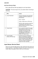
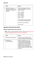
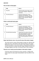
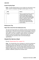
4045-XXX FRU 3 Motor does not turn, no gear error code 936 or User message 201 Paper Jam displays. Action Check the voltages at J3 on the engine board with the main motor cable connected. J3-1 - +24 V dc J3-2 - +24 V dc J3-3 - Ground J3-4 - Ground J3-5 - +2.5 V dc J3-7 - +5 V dc J3-9 - +5 V dc If any voltage is incorrect, replace the FRUs in the following order: main drive motor assembly engine board Operator Panel Service Check Operator Panel Buttons Service Check Note: Before continuing with this service check do the "Button Test" on page 3-9 and "Operator Panel Test" on page 3-21. FRU 1 Operator Panel Assembly 2 Engine Board (No buttons work) Action If any button fails the Button Test, replace the operator panel assembly. Check the voltage at J1-2. The voltage measures approximately +5 V dc with the controller board removed. If incorrect, replace the engine board. If correct, check the continuity of the operator panel cable. If incorrect, replace the cable. If correct, replace the operator panel assembly. 2-30 Service Manual
-
 1
1 -
2
-
3
-
4
-
5
-
6
-
7
-
8
-
9
-
10
-
11
-
12
-
13
-
14
-
15
-
16
-
17
-
18
-
19
-
20
-
21
-
22
-
23
-
24
-
25
-
26
-
27
-
28
-
29
-
30
-
31
-
32
-
33
-
34
-
35
-
36
-
37
-
38
-
39
-
40
-
41
-
42
-
43
-
44
-
45
-
46
-
47
-
48
-
49
-
50
-
 51
51 -
 52
52 -
 53
53 -
 54
54 -
 55
55 -
 56
56 -
 57
57 -
 58
58 -
 59
59 -
 60
60 -
 61
61 -
62
-
63
-
64
-
65
-
66
-
67
-
68
-
69
-
70
-
71
-
72
-
73
-
74
-
75
-
76
-
77
-
78
-
79
-
80
-
81
-
82
-
83
-
84
-
85
-
86
-
87
-
88
-
89
-
90
-
91
-
92
-
93
-
94
-
95
-
96
-
97
-
98
-
99
-
100
-
101
-
102
-
103
-
104
-
105
-
106
-
107
-
108
-
109
-
110
-
111
-
112
-
113
-
114
-
115
-
116
-
117
-
118
-
119
-
120
-
121
-
122
-
123
-
124
-
125
-
126
-
127
-
128
-
129
-
130
-
131
-
132
-
133
-
134
-
135
-
136
-
137
-
138
-
139
-
140
-
141
-
142
-
143
-
144
-
145
-
146
-
147
-
148
-
149
-
150
-
151
-
152
-
153
-
154
-
155
-
156
-
157
-
158
-
159
-
160
-
161
-
162
-
163
-
164
-
165
-
166
-
167
-
168
-
169
-
170
-
171
-
172
-
173
-
174
-
175
-
176
-
177
-
178
-
179
-
180
-
181
-
182
-
183
-
184
-
185
-
186
-
187
-
188
-
189
-
190
-
191
-
192
-
193
-
194
-
195
 |
 |
