Lexmark M410 Service Manual - Page 46
Dead Machine Service Check, Some force may be required to pull the LVPS loose from
 |
UPC - 734646261005
View all Lexmark M410 manuals
Add to My Manuals
Save this manual to your list of manuals |
Page 46 highlights
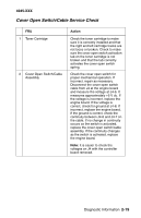
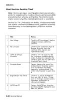
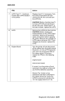
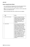
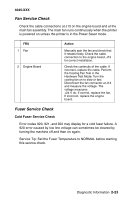
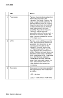
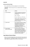
4045-XXX Dead Machine Service Check Note: Remove any paper handling options before servicing the printer for a dead machine condition. Observe all necessary ESD precautions when removing and handling the controller board, engine board or any of the installed option cards or assemblies. Service Tip: The LVPS uses a self-docking connector that mates with another connector mounted on the left side frame assembly. Some force may be required to pull the LVPS loose from the connector. FRU 1 Line Voltage 2 AC Line Cord 3 +24 V dc at Tray 2 Connector 4 Controller Board 5 Engine Board Test Points 6 LVPS Fuse F1 Action Check the AC line voltage. If the line voltage is incorrect, inform the customer. Check the line cord for any signs of damage. If correct, check the continuity of the line cord and replace if necessary. Check for +24 V dc at pin 7 of the tray 2 connector located under the printer. If +24 V dc is present at the connector, go to step 9. If +24 V dc is not present, go to step 4. Remove the controller board. Turn on the printer. If the printer powers on in the Hardware Test Mode, replace the controller board. If the printer does not power on, go to step 5. Check for +5 V dc at the TP5 test point and +24 V dc at the TP6 test point on the engine board. If correct, replace the engine board. If incorrect, go to step 6. Remove the LVPS from the printer and check fuse F1. Replace the fuse if the fuse is blown. 2-20 Service Manual
-
 1
1 -
2
-
3
-
4
-
5
-
6
-
7
-
8
-
9
-
10
-
11
-
12
-
13
-
14
-
15
-
16
-
17
-
18
-
19
-
20
-
21
-
22
-
23
-
24
-
25
-
26
-
27
-
28
-
29
-
30
-
31
-
32
-
33
-
34
-
35
-
36
-
37
-
38
-
39
-
40
-
 41
41 -
 42
42 -
 43
43 -
 44
44 -
 45
45 -
 46
46 -
 47
47 -
 48
48 -
 49
49 -
 50
50 -
 51
51 -
52
-
53
-
54
-
55
-
56
-
57
-
58
-
59
-
60
-
61
-
62
-
63
-
64
-
65
-
66
-
67
-
68
-
69
-
70
-
71
-
72
-
73
-
74
-
75
-
76
-
77
-
78
-
79
-
80
-
81
-
82
-
83
-
84
-
85
-
86
-
87
-
88
-
89
-
90
-
91
-
92
-
93
-
94
-
95
-
96
-
97
-
98
-
99
-
100
-
101
-
102
-
103
-
104
-
105
-
106
-
107
-
108
-
109
-
110
-
111
-
112
-
113
-
114
-
115
-
116
-
117
-
118
-
119
-
120
-
121
-
122
-
123
-
124
-
125
-
126
-
127
-
128
-
129
-
130
-
131
-
132
-
133
-
134
-
135
-
136
-
137
-
138
-
139
-
140
-
141
-
142
-
143
-
144
-
145
-
146
-
147
-
148
-
149
-
150
-
151
-
152
-
153
-
154
-
155
-
156
-
157
-
158
-
159
-
160
-
161
-
162
-
163
-
164
-
165
-
166
-
167
-
168
-
169
-
170
-
171
-
172
-
173
-
174
-
175
-
176
-
177
-
178
-
179
-
180
-
181
-
182
-
183
-
184
-
185
-
186
-
187
-
188
-
189
-
190
-
191
-
192
-
193
-
194
-
195
 |
 |
