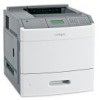
Lexmark T650 Service Manual
Lexmark T650 Manual
 |
View all Lexmark T650 manuals
Add to My Manuals
Save this manual to your list of manuals |
Lexmark T650 manual content summary:
- Lexmark T650 | Service Manual - Page 1
: September 17, 2009 Lexmark™ T650, T650n, T652dn, T654dn & T656dne Printer 4062-XXX • Table of contents • Start diagnostics • Safety and notices • Trademarks • Index Lexmark and Lexmark with diamond design are trademarks of Lexmark International, Inc., registered in the United States and/or other - Lexmark T650 | Service Manual - Page 2
at any time. Comments may be addressed to Lexmark International, Inc., Department D22X/002-1, 740 West New Circle Road, Lexington, Kentucky 40550, U.S.A or e-mail at [email protected]. Lexmark may use or distribute any of the information you supply in any way it believes appropriate - Lexmark T650 | Service Manual - Page 3
1-7 Paper types and weights supported by the output bins 1-7 Tools required 1-8 Acronyms 1-9 Diagnostic information 2-1 Start 2-1 Confirm the installation status 2-2 Power-on Reset sequence 2-2 Entering Diagnostics mode 2-2 User attendance messages 2-3 Error code table 1 2-14 Service - Lexmark T650 | Service Manual - Page 4
check 2-154 Sensor (mailbox empty) static jam service check 2-154 Sensor (toner empty) service check 2-155 NVRAM mismatch failure (950.00 through 950.29) service check 2-155 2-156 Image quality trouble 2-157 Printer Related Troubleshooting 2-157 Image quality symptoms 2-157 Image Quality - Lexmark T650 | Service Manual - Page 5
EXIT DIAGNOSTICS (models T650, T652, and T654 3-24 Configuration menu (CONFIG MENU) (models T650, T652, and T654 3-25 Entering Configuration Menu (models T650, T652, and T654 3-25 Available menus 3-25 Maintenance page count (Maint Cnt Value 3-25 Maintenance page counter reset (Reset Cnt 3-26 - Lexmark T650 | Service Manual - Page 6
(input tray 3-41 OUTPUT BIN TESTS 3-41 Feed Tests (output bins 3-41 Sensor Test (standard output bin 3-41 BASE SENSOR TEST 3-42 DEVICE TESTS 3-43 Quick Disk Test 3-43 Disk Test/Clean 3-43 PRINTER SETUP 3-44 Defaults 3-44 Printed Page Count 3-44 Permanent Page Count 3-44 Serial Number - Lexmark T650 | Service Manual - Page 7
Available menus 3-49 Maintenance Counter Value 3-49 Reset Maintenance Counter 3-50 Print Quality Pages 3-51 Reports 3-51 Menu Settings Page 3-51 Event Log 3-51 SIZE SENSING 3-52 Panel Menus 3-52 PPDS Emulation 3-52 Factory Defaults 3-54 Energy Conserve 3-54 Paper Prompts 3-55 Envelope - Lexmark T650 | Service Manual - Page 8
fuser unit assembly 3-74 Exit 3-74 Sensor (standard bin full 3-74 Drive 3-75 Main drive motor assembly 3-75 Redrive motor assembly 3-75 Electrical components and controller 3-76 Switch (printer front door interlock 3-76 Main cooling fan 3-76 Print cartridge cooling fan 3-76 Duplex cooling - Lexmark T650 | Service Manual - Page 9
239 paper jams (optional external duplex unit 3-100 Rear paper jams 3-100 Front paper jams 3-100 241-245 paper jams 3-101 250 paper jam 3-102 260 paper jam 3-103 271-279 paper jams 3-103 280 paper jam 3-104 281 paper jam 3-105 282 paper jam 3-105 283 staple jam 3-106 Security Reset Jumper - Lexmark T650 | Service Manual - Page 10
4062-XXX Duplex guide assembly, front removal (T652, T654 4-21 Fuser access door assembly removal (T650, T652, T654 4-22 Fuser drive release linkage removal (T650, T652, T654 4-23 Fuser unit assembly removal (T650, T652, T654 4-23 Fuser wiper cover assembly removal (T650, T652, T654 4-24 HVPS - Lexmark T650 | Service Manual - Page 11
card cover panel removal 4-137 High capacity stacker switch (media bin HP) removal 4-138 High capacity stacker sensor (media bin full) assembly removal 4-139 High capacity stacker sensor (media bin full) bracket assembly removal 4-139 High capacity stacker controller card assembly (upper - Lexmark T650 | Service Manual - Page 12
through) with cable removal 4-196 Tray roller catch assembly removal 4-196 Tray roller catch assembly removal 4-197 Upper interface cable assembly removal 4-197 Connector locations and connections 5-1 Connections 5-1 Preventive maintenance 6-1 Safety inspection guide 6-1 xii Service Manual - Lexmark T650 | Service Manual - Page 13
High capacity stacker 7-38 Assembly 20: Output expander 7-40 Assembly 21: Envelope feeder and external duplex 7-42 Assembly 22: RFID UHF Option assembly 7-44 Assembly 23: Miscellaneous 7-45 Assembly 24: Power cords 7-47 Assembly 25: Universal trays and accessories 7-48 Index I-1 Part number - Lexmark T650 | Service Manual - Page 14
4062-XXX xiv Service Manual - Lexmark T650 | Service Manual - Page 15
in the wavelength region of 770-795 nanometers. The laser system and printer are designed so there is never any human access to laser radiation above a Class I level during normal operation, user maintenance, or prescribed service condition. Laser Der Drucker erfüllt gemäß amtlicher Bestätigung der - Lexmark T650 | Service Manual - Page 16
galliumarsenid laser, som arbejder på bølgelængdeområdet 770-795 nanometer. Lasersystemet og printeren er udformet således, at mennesker aldrig udsættes for en laserstråling over Klasse I-niveau ved normal drift, brugervedligeholdelse eller obligatoriske servicebetingelser. xvi Service Manual - Lexmark T650 | Service Manual - Page 17
utsätts för laserstrålning över Klass I-nivå vid normal användning, underhåll som utförs av användaren eller annan föreskriven serviceåtgärd. Laser-melding Skriveren er godkjent i USA etter kravene i DHHS 21 CFR, underkapittel J, for klasse I (1) laserprodukter, og er i andre land godkjent som et - Lexmark T650 | Service Manual - Page 18
4062-XXX Avís sobre el Làser Segons ha estat certificat als Estats Units, aquesta impressora compleix els requisits de DHHS 21 CFR, apartat J, pels productes làser de classe I (1), les tasques de manteniment d'usuari ni durant els serveis que satisfacin les condicions prescrites. xviii Service Manual - Lexmark T650 | Service Manual - Page 19
4062-XXX Notices and safety information xix - Lexmark T650 | Service Manual - Page 20
4062-XXX xx Service Manual - Lexmark T650 | Service Manual - Page 21
IF THE BATTERY IS REPLACED BY AN INCORRECT TYPE. Discard used batteries according to the battery manufacturer's instructions and local regulations. use of unauthorized replacement parts. • The maintenance information for this product has been prepared for use by a professional service person and - Lexmark T650 | Service Manual - Page 22
peligro y tomar las precauciones necesarias. • PRECAUCIÓN: este símbolo indica que el voltaje de la parte del equipo con la que está trabajando es peligroso. Antes de empezar, desenchufe el equipo o de estar ligado à corrente eléctrica para realizar a tarefa necessária. xxii Service Manual - Lexmark T650 | Service Manual - Page 23
producte. El personal professional ha d'estar-ne assabentat i prendre les mesures convenients. • PRECAUCIÓ: aquest símbol indica que el voltatge de la part de l'equip amb la qual esteu treballant és perillós. Abans de començar, desendolleu l'equip o extremeu les precaucions si, per treballar - Lexmark T650 | Service Manual - Page 24
, and service checks used to isolate failing field replaceable units (FRUs). 3. Diagnostic aids contains tests and checks used to locate or repeat symptoms of printer problems. 4. Repair information provides instructions for making printer adjustments and removing and installing FRUs. 5. Connector - Lexmark T650 | Service Manual - Page 25
Network Network Maintenance approach The diagnostic information in this manual leads you to the correct field replaceable unit (FRU) or part. Use the service error codes, user status messages, user error messages, service checks, and diagnostic aids to determine the printer problem and repair - Lexmark T650 | Service Manual - Page 26
- Duplex option-250-sheet (external) - Duplex option-550-sheet (internal on duplex versions of T652 and T654) - Output expander - High-capacity output stacker - StapleSmart™ Finisher - 5-bin Mailbox - Vertical Kiosk Presenter - Horizontal Kiosk Presenter - RFID UHF (only for T654) 1-2 Service Manual - Lexmark T650 | Service Manual - Page 27
configurations Basic model The following illustration shows the basic printer model. 1 2 4 Feature 1 Standard exit bin 2 Printer control panel 3 Multipurpose feeder 4 Standard tray (Tray 1) 1Based on 75 g/m2 (20 lb.) paper. Paper Capacity1 250- or 550-sheet NA 100 sheets 250- or - Lexmark T650 | Service Manual - Page 28
additional furniture for stability. You must use either a printer stand or printer base if you are using a 2000-sheet tray, a duplex unit, and an input option, or more than one input option. For more information, see www.lexmark.com/publications/furniture_safety. 1 2 3 4 5 6 7 8 9 1-4 Service Manual - Lexmark T650 | Service Manual - Page 29
to two 5-bin mailbox units are supported. 3 The printer supports up to three output expander units, or one output expander combined with one 5bin mailbox, one high capacity output expander (not depicted), or one stapler unit (not depicted). 4 Optional external duplex unit for the T650 model. All - Lexmark T650 | Service Manual - Page 30
standard and optional paper sources and the types of paper they support. Note: For an unlisted paper size, select the closest larger listed size. Paper sizes supported by the printer Paper Duplex unit x x x x x x x x x x x x x x x x x x x x x x x x x x 1-6 Service Manual - Lexmark T650 | Service Manual - Page 31
Multipurpose feeder Duplex unit Other Envelope 98 x 162 mm x (3.9 x 6.4 in.) to 176 x 250 mm (6.9 x 9.8 in.) 1This size appears in the Paper Size menu only when the paper source does not support size sensing or when size sensing is turned off. 2Only the standard exit bin supports this size - Lexmark T650 | Service Manual - Page 32
finisher supports 60-176 g/m2 (16-47 lb) paper weights. Optional hardware Paper type Standard exit bin (350 or 550 sheets) Output Expander (550 sheets) or High Capacity Output stacker (1850 sheets) 5-Bin Mailbox (500 sheets)1 StapleSmart II Finisher (500 sheets)2 Paper x x x x • Plain - Lexmark T650 | Service Manual - Page 33
Enhanced Data Out Electrically Erasable Programable Read-Only Memory Electrophotographic process Erasable Programmable Read-Only Memory Electrostatic Discharge Field Replaceable Unit Gigabyte High-capacity Input Tray High Voltage Power Supply Internal Tray Card Light Amplification by Stimulated - Lexmark T650 | Service Manual - Page 34
4062-XXX 1-10 Service Manual - Lexmark T650 | Service Manual - Page 35
like to remove static electricity from their body, grounding their body while working. Go to "Handling ESD-sensitive parts" on page 4-1. Note: There may be printer error messages that are not contained in this service manual. Call your next level support for assistance. Diagnostic information 2-1 - Lexmark T650 | Service Manual - Page 36
to the User's Guide for proper installation. Power-on Reset sequence The following is an example of the events that occur during the POR sequence: 1. Turn the machine on. 2. The Lexmark splash screen appears with a progress bar in the center until the code is loaded. 3. The fuser cooling fan turns - Lexmark T650 | Service Manual - Page 37
Timeout Invalid Refill Change Cartridge Defective Cartridge Cartridge part number X unsupported by device Short Paper Description/Action The system detects a firmware component that is no longer responding. Message is cleared when a new print cartridge is installed. Error code 31 displays when the - Lexmark T650 | Service Manual - Page 38
: • Press to clear the message. To perform the defragment operation: - Delete fonts, macros, and other data in RAM. - Install additional printer memory. • Press until Busy/ Waiting appears. The following actions are available: - Cancel Job - Reset Printer - Reset Active Bin 2-4 Service Manual - Lexmark T650 | Service Manual - Page 39
the defragment operation - Delete fonts, macros, and other data in RAM - Install additional memory • Press to display Busy/ Waiting. The following functions may be available: - Cancel Job - Reset Printer Reset Active Bin The following actions may be taken: • Press to clear the message and - Lexmark T650 | Service Manual - Page 40
. 2. Check the RFID firmware card, RFID interface card, RFID cable, and RFID option for correct installation. Go to "High capacity input tray (HCIT) pick arm bracket assembly removal" on page 4-130. 3. Replace the RFID UHF option. 1. These error codes most likely indicate a problem with the customer - Lexmark T650 | Service Manual - Page 41
location parameters: tag is not compatible with printer Unsupported SA Code Invalid Power setting Unsupported Feature Generic run-time reader error Reader response timeout Garbled or short response from reader 1. These error codes most likely indicate a problem with the customer's datastream, and - Lexmark T650 | Service Manual - Page 42
's datastream. 2. Check the RFID firmware card, RFID interface card, RFID cable, and RFID option for correct installation. Go to "High capacity input tray (HCIT) pick arm bracket assembly removal" on page 4-130. 3. Replace the RFID UHF option. Install a new toner cartridge that matches the correct - Lexmark T650 | Service Manual - Page 43
Error code or message 52 54 54 54 55 56 Error contents Flash Full Serial Option [x] Error Std Network Software Error Network [x] Software Error Unsupported Option in Slot [x] Parallel Port [x] Disabled Description/Action This message displays when the printer detects an unformatted flash at power - Lexmark T650 | Service Manual - Page 44
RFID cable, and RFID option for correct installation. Go to "High capacity input tray (HCIT) pick arm bracket assembly removal" on page 4-130. 3. Replace the RFID UHF option. 1. Turn off and unplug the printer. 2. Remove the excess bins. 3. Plug in the printer, and turn it on. 2-10 Service Manual - Lexmark T650 | Service Manual - Page 45
59 Incompatible Duplex 59 Incompatible Envelope Feeder Description/Action This error code displays when too many disks are attached to the printer. This error code displays when too many user flash memory options or too many optional firmware cards have been installed. User can power off and - Lexmark T650 | Service Manual - Page 46
displays this message at each 300K page count interval. It is necessary to replace the fuser assembly, transfer roller, charge roll, and pick rolls at this interval to maintain the print quality and reliability of the printer. The parts are available as a maintenance kit. For more information, go to - Lexmark T650 | Service Manual - Page 47
4062 Error code or message 88 Error contents Cartridge Low 88 Cartridge Nearly Low 88 Replace Cartridge Description/Action Possible repair actions This IR is displayed when cartridge low occurs and the cartridge low alarm is activated. If cartridge alarm is not activated, this is not an - Lexmark T650 | Service Manual - Page 48
page 2-126. Go to sensor (input) late jam service check. See "Sensor (input) late jam service check." on page 2-129. 1. Fan the media and ensure it is properly installed. 2. Go to sensor (input) early jam service check. See "Sensor (input) early jam service check" on page 2-133. 2-14 Service Manual - Lexmark T650 | Service Manual - Page 49
Laser power signal error The printhead laser power signal has failed Possible repair actions 1. Check all connections on the printhead. 2. Check all connections on the main drive motor assembly. 3. Replace the main drive motor assembly if problem remains. Go to "Output cover assembly removal (T650 - Lexmark T650 | Service Manual - Page 50
"Sensor (input) early jam service check" on page 2-133. 1. Remove all media present in media path. 2. Check all connections on the printhead. 3. Check all connections on the system card assembly. 4. Replace the printhead if problem remains. Go to "Printhead assembly removal (T650)" on page 4-60 or - Lexmark T650 | Service Manual - Page 51
Fan the media and ensure it is properly installed. 2. Go to sensor (input) early jam service check. See "Sensor (input) early jam service check" on page 2-133. 1. Inspect print cartridge pulse wheel for damage and replace if needed. 2. Check the sensor (toner empty) for proper operation. See "Sensor - Lexmark T650 | Service Manual - Page 52
See "Sensor (input) lingering jam service check." on page 2-132. Go to sensor (input) lingering jam service check. See "Sensor (input) lingering jam service check." on page 2-132. Go to sensor (fuser output) service check. See "Sensor (fuser output) service check" on page 2-126. 2-18 Service Manual - Lexmark T650 | Service Manual - Page 53
Replace the main drive motor assembly if problem remains. Go to "Output cover assembly removal (T650, T652, T654)" on page 4-54. Go to sensor (fuser output) late jam service check. See "Sensor (fuser output) late jam service check." on page 2-135. If problem remains, a type 2 fuser can be installed - Lexmark T650 | Service Manual - Page 54
Replace the main drive motor assembly if problem remains. Go to "Output cover assembly removal (T650, T652, T654)" on page 4-54. Go to sensor (fuser output) late jam service check. See "Sensor (fuser output) late jam service check." on page 2-135. If problem remains, a type 2 fuser can be installed - Lexmark T650 | Service Manual - Page 55
Replace the main drive motor assembly if problem remains. Go to "Output cover assembly removal (T650, T652, T654)" on page 4-54. Go to sensor (fuser output) late jam service check. See "Sensor (fuser output) late jam service check." on page 2-135. If problem remains, a type 2 fuser can be installed - Lexmark T650 | Service Manual - Page 56
on the system card assembly. 4. Replace the main drive motor assembly if problem remains. Go to "Output cover assembly removal (T650, T652, T654)" on page 4-54. Go to sensor (fuser output) late jam service check. See "Sensor (fuser output) late jam service check." on page 2-135. 2-22 Service Manual - Lexmark T650 | Service Manual - Page 57
on the system card assembly. 3. Replace the printhead assembly if problem remains. 4. Replace the system card assembly if problem remains. Go to "System card assembly removal (T650, T652, T654, T656)" on page 4-76. Go to sensor (narrow media) late jam service check. See "Sensor (narrow media - Lexmark T650 | Service Manual - Page 58
4062 Error code or message 202.00 Error contents Paper jam around fuser exit or redrive area. Type 1 fuser 202.01 202.02 Sensor (fuser output) lingering jam. Destination is standard bin. Type 1 fuser Sensor (fuser output) lingering jam. Type 1 fuser 202.03 Sensor (narrow media) static jam Type - Lexmark T650 | Service Manual - Page 59
4062 Error code or message 202.10 Error contents Sensor (fuser output) lingering jam. Destination is output option. Type 1 fuser 202.11 Sensor (fuser output) lingering jam. Destination is standard bin. Type 1 fuser 202.12 Sensor (fuser output) lingering jam. Destination is output option. Type - Lexmark T650 | Service Manual - Page 60
2 fuser 202.32 Sensor (fuser output) lingering jam. Type 2 fuser 202.34 Sensor (fuser output) lingering jam. Type 2 fuser 202.35 202.36 Sensor (fuser output) lingering jam. Destination is output option. Type 2 fuser Sensor (fuser output) lingering jam. Destination is standard bin. Type 2 fuser - Lexmark T650 | Service Manual - Page 61
sequence. 202.50 Paper jam around fuser exit or redrive area. Type 1 fuser Fuser page count has exceeded life Page may be jammed in fuser exit or redrive area. 202.51 202.52 202.53 Sensor (fuser output) lingering jam. Destination is standard bin. Type 1 fuser Fuser page count has exceeded life - Lexmark T650 | Service Manual - Page 62
jam. Type 1 fuser Fuser page count has exceeded life. Sensor (fuser output) lingering jam. Destination is output option. Type 1 fuser Fuser page count has exceeded life. Sensor (fuser output) lingering jam. Destination is standard bin. Type 1 fuser Fuser page count has exceeded life. Sensor (fuser - Lexmark T650 | Service Manual - Page 63
202.79 Error contents Sensor (fuser output) static jam and Sensor (narrow media) static jam Type 1 fuser Fuser page count has exceeded life. Paper jam around fuser exit or redrive area. Type 2 fuser Fuser page count has exceeded life. Sensor (fuser output) lingering jam. Destination is standard bin - Lexmark T650 | Service Manual - Page 64
jam. Type 2 fuser Fuser page count has exceeded life. Sensor (fuser output) lingering jam. Destination is output option. Type 2 fuser Fuser page count has exceeded life. Sensor (fuser output) lingering jam. Destination is standard bin. Type 2 fuser Fuser page count has exceeded life. Sensor (fuser - Lexmark T650 | Service Manual - Page 65
Error code or message 202.99 Error contents Fuser ID chip failure 203.00 Paper jam around redrive area. 203.01 Internal duplex drive motor control failure. Internal duplex 203.08 Redrive motor load error Description/Action Possible repair actions The system does not recognize the ID chip - Lexmark T650 | Service Manual - Page 66
4062 Error code or message 203.10 203.18 203.20 230.00 230.01 Error contents Redrive motor control failure. Media tray 1 Redrive motor assembly underspeed error. Redrive motor lost encoder failure Paper jam around internal duplex. Source = Internal duplex Sensor (duplex input) lingering jam Source - Lexmark T650 | Service Manual - Page 67
"Sensor (input) late jam service check." on page 2-129. 1. Remove all media present in media path. 2. Check all connections on the duplex media entrance drive motor assembly. 3. Check all connections on the system card assembly. 4. Replace the duplex drive motor assembly if problem remains. Go to - Lexmark T650 | Service Manual - Page 68
4062 Error code or message 230.10 Error contents Internal duplex drive motor control failure. Source = Internal duplex 230.13 230.14 sensor (duplex input) static jam Source = Internal duplex Paper jam around internal duplex. Source = Internal duplex 230.18 Internal duplex drive motor assembly - Lexmark T650 | Service Manual - Page 69
connections on the system card assembly. 4. Replace the duplex drive motor assembly if problem remains. Go to "Duplex drive motor assembly removal (T652, T654)" on page 4-19. Go to sensor (duplex input) late jam service check. See "Sensor (duplex input) late jam service check." on page 2-141. Go to - Lexmark T650 | Service Manual - Page 70
is properly installed. 5. Check sensor (duplex exit) for proper operation.See "Sensor (duplex exit) service check (external duplex only)" on page 2-128. 6. Replace the external duplex assembly if problem remains. Go to sensor (input) late jam service check. See "Sensor (input) late jam service check - Lexmark T650 | Service Manual - Page 71
4062 Error code or message 237.07 238.00 238.01 238.02 238.03 Error contents Paper jam around external duplex Source = External duplex. External duplex sensor static jam Source = External duplex Sensor (duplex input) static jam Source = External duplex Sensor (duplex exit) static jam Source = - Lexmark T650 | Service Manual - Page 72
error or timing error. Possible repair actions 1. Remove all media present in media path. 2. Replace the external duplex assembly if problem remains. 1. Remove all media present in media path. 2. Go to sensor (duplex input) static jam service check. See "Sensor (duplex input) lingering jam service - Lexmark T650 | Service Manual - Page 73
in media path. 4. Ensure the external duplex assembly is properly installed. 5. Ensure the rear door of the external duplex is fully closed. 6. Check all connections on the external duplex assembly. 7. Replace the external duplex assembly if problem remains. 1. Remove all media present in - Lexmark T650 | Service Manual - Page 74
for obstructions in media path. 4. Ensure the external duplex assembly is properly installed. 5. Ensure the rear door of the external duplex is fully closed. 6. Check all connections on the external duplex assembly. 7. Replace the external duplex assembly if problem remains. 2-40 Service Manual - Lexmark T650 | Service Manual - Page 75
is properly installed. 5. Ensure the rear door of the external duplex is fully closed. 6. Check all connections on the external duplex assembly. 7. Replace the external duplex assembly if problem remains. Go to sensor (input) late jam service check. See "Sensor (input) late jam service check." on - Lexmark T650 | Service Manual - Page 76
, X652, X654, and X656)" on page 4-49. 6. Replace system card assembly if problem remains. Go to "System card assembly removal (T650, T652, T654, T656)" on page 4-76. Go to sensor (input) late jam service check. See "Sensor (input) late jam service check." on page 2-129. 1. Remove all media present - Lexmark T650 | Service Manual - Page 77
4062 Error code or message 241.08 Error contents Pick motor load error Source = Media tray 1 Description/Action The pick motor has failed or caused high mechanical load due to paper jam or bind. 241.10 Sensor (input) late jam Source = Tray 1 The media is late reaching the sensor (input) within - Lexmark T650 | Service Manual - Page 78
49. 6. Replace system card assembly if problem remains. Go to "System card assembly removal (T650, T652, installation. 3. Check for obstructions in media path. Go to sensor (pass through) late jam service check. See "Sensor (pass through) late jam service check" on page 2-145. 2-44 Service Manual - Lexmark T650 | Service Manual - Page 79
4062 Error code or message 242.03 242.04 242.05 242.06 242.08 242.09 242.10 242.13 242.16 242.17 Error contents Sensor (pass through) late jam Source = Tray 2 Sensor (pass through) late jam Source = Tray 2 Sensor (pass through) late jam Source = Tray 2 Sensor (pass through) late jam Source = Tray - Lexmark T650 | Service Manual - Page 80
Check the media out actuator for damage. 2. Replace the media out actuator if problem remains. Go to "Tray roller catch assembly removal (T650, T652, T654)" on page 4-81. Go to sensor (pass through) static jam service check. See "Sensor (pass through) static jam service check" on page 2-147. Go to - Lexmark T650 | Service Manual - Page 81
pass through) lingering jam service check." on page 2-146. 1. Ensure the HCIT media tray assembly is properly inserted into the machine. 2. Check the HCIT tray lift motor assembly for binding or damage. 3. Replace the HCIT tray lift drive motor assembly if problem remains. Go to "High capacity input - Lexmark T650 | Service Manual - Page 82
4062 Error code or message 242.65 Error contents Pick motor load error Source = Media tray 2 Description/Action The pick motor has failed or caused high mechanical load due to paper jam or bind. 242.66 Pick motor underspeed failure Source = Media tray 2 The pick motor does not rotate at the - Lexmark T650 | Service Manual - Page 83
remains. Go to "Operator panel door assembly removal (models X651, X652, X654, and X656)" on page 4-49. 6. Replace system card assembly if problem remains. Go to "System card assembly removal (T650, T652, T654, T656)" on page 4-76. 1. Remove all media present in media path. 2. Ensure media tray is - Lexmark T650 | Service Manual - Page 84
Replace system card assembly if problem remains. Go to "System card assembly removal (T650, T652, T654, T656)" on page 4-76. 1. Remove all media present in media path. 2. Check media for proper installation. 3. Check for obstructions in media path. Go to sensor (pass through) late jam service check - Lexmark T650 | Service Manual - Page 85
(pass through) late jam service check" on page 2-145. 1. Remove all media present in media path. 2. Close all media trays. Turn the machine off/on. Turn the machine off/on. 1. Check the size sensing fingers on the media tray for damage 2. Replace the media tray assembly if problem remains. 3. Check - Lexmark T650 | Service Manual - Page 86
pass through) lingering jam service check." on page 2-146. 1. Ensure the HCIT media tray assembly is properly inserted into the machine. 2. Check the HCIT tray lift motor assembly for binding or damage. 3. Replace the HCIT tray lift drive motor assembly if problem remains. Go to "High capacity input - Lexmark T650 | Service Manual - Page 87
high mechanical load due to paper jam or bind. Possible repair actions 1. Ensure the HCIT media tray assembly is properly inserted into the machine. 2. Check the HCIT tray lift motor assembly for binding or damage. 3. Replace the HCIT tray lift drive motor assembly if problem remains. Go to "High - Lexmark T650 | Service Manual - Page 88
. 5. Replace the pick arm assembly if problem remains. Go to "Operator panel door assembly removal (models X651, X652, X654, and X656)" on page 4-49. 6. Replace system card assembly if problem remains. Go to "System card assembly removal (T650, T652, T654, T656)" on page 4-76. 2-54 Service Manual - Lexmark T650 | Service Manual - Page 89
Replace system card assembly if problem remains. Go to "System card assembly removal (T650, T652, T654, T656)" on page 4-76. 1. Remove all media present in media path. 2. Check media for proper installation. 3. Check for obstructions in media path. Go to sensor (pass through) late jam service check - Lexmark T650 | Service Manual - Page 90
) static jam service check" on page 2-147. Go to sensor (pass through) late jam service check. See "Sensor (pass through) late jam service check" on page 2-145. 1. Remove all media present in media path. 2. Close all media trays. Turn the machine off/on. Turn the machine off/on. 2-56 Service Manual - Lexmark T650 | Service Manual - Page 91
Check the media out actuator for damage. 2. Replace the media out actuator if problem remains. Go to "Tray roller catch assembly removal (T650, T652, T654)" on page 4-81. Go to sensor (pass through) static jam service check. See "Sensor (pass through) static jam service check" on page 2-147. Go to - Lexmark T650 | Service Manual - Page 92
4062 Error code or message 244.49 Error contents HCIT tray lift motor stalled failure Source = Tray 4 or damage. 3. Replace the HCIT tray lift drive motor assembly if problem remains. Go to "High capacity input tray (HCIT) tray lift drive motor assembly removal" on page 4-125. 2-58 Service Manual - Lexmark T650 | Service Manual - Page 93
Error code or message 244.65 Error contents Pick motor load error Source = Media tray 4 Description/Action The pick motor has failed or caused high mechanical load due to paper jam page 4-49. 7. Replace system card assembly if problem remains. Go to "System card assembly removal (T650, T652, T654, - Lexmark T650 | Service Manual - Page 94
. 5. Replace the pick arm assembly if problem remains. Go to "Operator panel door assembly removal (models X651, X652, X654, and X656)" on page 4-49. 6. Replace system card assembly if problem remains. Go to "System card assembly removal (T650, T652, T654, T656)" on page 4-76. 2-60 Service Manual - Lexmark T650 | Service Manual - Page 95
Replace system card assembly if problem remains. Go to "System card assembly removal (T650, T652, T654, T656)" on page 4-76. 1. Remove all media present in media path. 2. Check media for proper installation. 3. Check for obstructions in media path. Go to sensor (pass through) late jam service check - Lexmark T650 | Service Manual - Page 96
size) if problem remains. Go to "Switch (media size) assembly removal (T650, T652, T654)" on page 4-74. 1. Check the media out actuator for damage. 2. Replace the media out actuator if problem remains. Go to "Tray roller catch assembly removal (T650, T652, T654)" on page 4-81. 2-62 Service Manual - Lexmark T650 | Service Manual - Page 97
pass through) lingering jam service check." on page 2-146. 1. Ensure the HCIT media tray assembly is properly inserted into the machine. 2. Check the HCIT tray lift motor assembly for binding or damage. 3. Replace the HCIT tray lift drive motor assembly if problem remains. Go to "High capacity input - Lexmark T650 | Service Manual - Page 98
high mechanical load due to paper jam or bind. Possible repair actions 1. Ensure the HCIT media tray assembly is properly inserted into the machine. 2. Check the HCIT tray lift motor assembly for binding or damage. 3. Replace the HCIT tray lift drive motor assembly if problem remains. Go to "High - Lexmark T650 | Service Manual - Page 99
4062 Error code or message 245.66 Error contents Pick motor underspeed failure Source = Media tray (models X651, X652, X654, and X656)" on page 4-49. 6. Replace system card assembly if problem remains. Go to "System card assembly removal (T650, T652, T654, T656)" on page 4-76. 1. Remove all media - Lexmark T650 | Service Manual - Page 100
X656)" on page 4-49. 6. Replace system card assembly if problem remains. Go to "System card assembly removal (T650, T652, T654, T656)" on page 4-76. Go to sensor (input) service check. See "Sensor (input) service check" on page 2-126. Go to sensor (input) late jam service check. See "Sensor (input - Lexmark T650 | Service Manual - Page 101
envelope feeder area. Mechanical feed error or timing error. Possible repair actions Go to sensor (input) late jam service check. See "Sensor (input) late jam service check." on page 2-129. Go to sensor (input) late jam service check. See "Sensor (input) late jam service check." on page 2-129. Go - Lexmark T650 | Service Manual - Page 102
connections on the envelope feeder. 6. Check all connections on the system card assembly. 7. Replace the envelope feeder assembly if problem remains. 8. Replace system card assembly if problem remains. Go to "System card assembly removal (T650, T652, T654, T656)" on page 4-76. 2-68 Service Manual - Lexmark T650 | Service Manual - Page 103
all media present in media path. 3. Replace the envelope feeder is problem remains. Go to sensor (input) late jam service check. See "Sensor (input) late jam service check." on page 2-129. Go to sensor (input) late jam service check. See "Sensor (input) late jam service check." on page 2-129. Go to - Lexmark T650 | Service Manual - Page 104
4062 Error code or message 271.04 x = bin number 271.05 x = bin number 27x.14 x = bin number Error contents Sensor (output pass through) late jam Applies to: High capacity output Output expander Sensor (output pass through) lingering jam Applies to: High capacity output Output expander Sensor ( - Lexmark T650 | Service Manual - Page 105
4062 Error code or message 27x.50 x = bin number Error contents Sensor (output pass through) lingering jam Applies to: and right) removal" on page 4-187. 4. Replace the output option if problem remains. See "Sensor (output pass through) late jam service check" on page 2-150 The sensor (right - Lexmark T650 | Service Manual - Page 106
with the output option. 1. Turn the machine off/on. 2. Replace the output option if problem remains. The media reached the sensor (stapler pass through) but did not clear it in the specified time. See "Sensor (stapler pass through) lingering jam service check" on page 2-149. 2-72 Service Manual - Lexmark T650 | Service Manual - Page 107
the stapler assembly. Go to "SFP stapler assembly stapler unit assembly removal" on page 4-182. 4. Manually rotate the drive gears and reset the stapler. Remove all jammed staples then reinstall the stapler assembly. 5. If problem remains, replace the stapler assembly. Go to "SFP stapler assembly - Lexmark T650 | Service Manual - Page 108
unit assembly removal" on page 4-182. 4. Manually rotate the drive gears and reset the stapler. Remove all jammed staples then reinstall the stapler assembly. 5. If problem remains, replace the stapler assembly. Go to "SFP stapler assembly stapler unit assembly removal" on page 4-182. 2-74 Service - Lexmark T650 | Service Manual - Page 109
the stapler assembly. Go to "SFP stapler assembly stapler unit assembly removal" on page 4-182. 4. Manually rotate the drive gears and reset the stapler. Remove all jammed staples then reinstall the stapler assembly. 5. If problem remains, replace the stapler assembly. Go to "SFP stapler assembly - Lexmark T650 | Service Manual - Page 110
4062 Error code or message 28x.41 x = bin number 28x.42 x = bin number Error contents Left tamper does not move Replace the sensor (tamper HP). Go to "SFP stapler assembly sensor (tamper HP left and right) removal" on page 4-187. 4. Replace the output option if problem remains. 2-76 Service Manual - Lexmark T650 | Service Manual - Page 111
4062 Error code or message 28x.43 x = bin number 28x.44 x = bin number 28x.45 x = bin number 28x.46 x = bin number 28x.47 x = bin number Error contents Right tamper does not move to home position failure. Applies to: StapleSmart finisher Eject home position jam Applies to: StapleSmart finisher - Lexmark T650 | Service Manual - Page 112
.48 x = bin number Error contents Deflector gate transition to output option not detected Applies to: StapleSmart finisher 28x.49 x = bin number Deflector gate transition to standard bin not detected Applies to: StapleSmart finisher 28x.50 x = bin number Left tamper home position jam Applies to - Lexmark T650 | Service Manual - Page 113
4062 Error code or message 28x.51 x = bin number Error contents Right tamper home position jam Applies to: StapleSmart finisher 28x.52 x = bin number 28x.53 x = bin number 28x.54 x = bin number 28x.55 x = bin number 28x.56 x = bin number 28x.57 x = bin number Paddle control motor timer error - Lexmark T650 | Service Manual - Page 114
the stapler assembly. Go to "SFP stapler assembly stapler unit assembly removal" on page 4-182. 4. Manually rotate the drive gears and reset the stapler. Remove all jammed staples then reinstall the stapler assembly. 5. If problem remains, replace the stapler assembly. Go to "SFP stapler assembly - Lexmark T650 | Service Manual - Page 115
the stapler assembly. Go to "SFP stapler assembly stapler unit assembly removal" on page 4-182. 4. Manually rotate the drive gears and reset the stapler. Remove all jammed staples then reinstall the stapler assembly. 5. If problem remains, replace the stapler assembly. Go to "SFP stapler assembly - Lexmark T650 | Service Manual - Page 116
removal" on page 4-182. 4. Manually rotate the drive gears and reset the stapler and remove all jammed staples then reinstall the stapler assembly. 5. If problem remains, replace the stapler assembly. Go to "SFP stapler assembly stapler unit assembly removal" on page 4-182. 2-82 Service Manual - Lexmark T650 | Service Manual - Page 117
Error code or message 28x.71 x = bin number 281.72 x = bin number 900.xx 901xx Error contents Deflector gate transition to standard bin not detected Applies to: StapleSmart finisher Sensor (media in stapler) static jam Applies to: StapleSmart finisher System software error System software error - Lexmark T650 | Service Manual - Page 118
the problem is system software related, or if the customer is sending a corrupted print job. 2. Check all connections on the system card assembly. 3. Replace the system card assembly if problem remains. Go to "System card assembly removal (T650, T652, T654, T656)" on page 4-76. 2-84 Service Manual - Lexmark T650 | Service Manual - Page 119
Error contents RIP interface driver error Pick arm motor stalled failure Pick arm motor overrun failure Pick arm motor underspeed failure Pick arm motor overspeed failure Description/Action Code 3. Replace the system card assembly if problem remains. Go to "System card assembly removal (T650, T652, - Lexmark T650 | Service Manual - Page 120
, T654)" on page 4-19. 1. Check all the connections on the duplex drive motor assembly. 2. Check all the connections on the system card assembly. 3. Replace the duplex drive motor assembly if problem remains. Go to "Duplex drive motor assembly removal (T652, T654)" on page 4-19. 2-86 Service Manual - Lexmark T650 | Service Manual - Page 121
19. 1. Turn the machine off/on and ensure the fuser unit assembly is properly installed. 2. Ensure the proper voltage fuser is installed in the machine. 3. Replace the fuser unit assembly if problem remains. Go to "Fuser unit assembly removal (T650, T652, T654)" on page 4-23. 1. Turn the machine off - Lexmark T650 | Service Manual - Page 122
23. 1. Turn the machine off/on and ensure the fuser unit assembly is properly installed. 2. Ensure the proper voltage fuser is installed in the machine. 3. Replace the fuser unit assembly if problem remains. Go to "Fuser unit assembly removal (T650, T652, T654)" on page 4-23. 1. Turn the machine off - Lexmark T650 | Service Manual - Page 123
31. 1. Turn the machine off/on and ensure the fuser unit assembly is properly installed. 2. Ensure the proper voltage fuser is installed in the machine. 3. Replace the fuser unit assembly if problem remains. Go to "Fuser unit assembly removal (T650, T652, T654)" on page 4-23. 1. Turn the machine off - Lexmark T650 | Service Manual - Page 124
4-23. 1. Turn the machine off/on and ensure the fuser unit assembly is properly installed. 2. Ensure the proper voltage fuser is installed in the machine. 3. Replace the fuser unit assembly if problem remains. Go to "Fuser unit assembly removal (T650, T652, T654)" on page 4-23. 2-90 Service Manual - Lexmark T650 | Service Manual - Page 125
/on and ensure the fuser unit assembly is properly installed. 2. Ensure the proper voltage fuser is installed in the machine. 3. Check all connections on the fuser and LVPS card assembly. 4. Replace the fuser unit assembly if problem remains. Go to "Fuser unit assembly removal (T650, T652, T654)" on - Lexmark T650 | Service Manual - Page 126
when heating to desired temperature after slope change within standby control only. Possible repair actions Replace the fuser unit assembly if problem remains. Go to "Fuser unit assembly removal (T650, T652, T654)" on page 4-23. Replace the fuser unit assembly if problem remains. Go to "Fuser unit - Lexmark T650 | Service Manual - Page 127
23. 1. Turn the machine off/on and ensure the fuser unit assembly is properly installed. 2. Ensure the proper voltage fuser is installed in the machine. 3. Replace the fuser unit assembly if problem remains. Go to "Fuser unit assembly removal (T650, T652, T654)" on page 4-23. 1. Turn the machine off - Lexmark T650 | Service Manual - Page 128
/on and ensure the fuser unit assembly is properly installed. 2. Ensure the proper voltage fuser is installed in the machine. 3. Check all connections on the fuser and LVPS card assembly. 4. Replace the fuser unit assembly if problem remains. Go to "Fuser unit assembly removal (T650, T652, T654)" on - Lexmark T650 | Service Manual - Page 129
/on and ensure the fuser unit assembly is properly installed. 2. Ensure the proper voltage fuser is installed in the machine. 3. Check all connections on the fuser and LVPS card assembly. 4. Replace the fuser unit assembly if problem remains. Go to "Fuser unit assembly removal (T650, T652, T654)" on - Lexmark T650 | Service Manual - Page 130
actions 1. Turn the machine off/on and ensure the fuser unit assembly is properly installed. 2. Ensure the proper voltage fuser is installed in the machine. 3. Replace the fuser unit assembly if problem remains. Go to "Fuser unit assembly removal (T650, T652, T654)" on page 4-23. 1. Turn the machine - Lexmark T650 | Service Manual - Page 131
/on and ensure the fuser unit assembly is properly installed. 2. Ensure the proper voltage fuser is installed in the machine. 3. Check all connections on the fuser and LVPS card assembly. 4. Replace the fuser unit assembly if problem remains. Go to "Fuser unit assembly removal (T650, T652, T654)" on - Lexmark T650 | Service Manual - Page 132
removal (T652, T654)" on page 4-31. Replace the fuser unit assembly if problem remains. Go to "Fuser unit assembly removal (T650, T652, T654)" on page 4-23. Replace the fuser unit assembly if problem remains. Go to "Fuser unit assembly removal (T650, T652, T654)" on page 4-23. 2-98 Service Manual - Lexmark T650 | Service Manual - Page 133
fuser unit assembly if problem remains. Go to "Fuser unit assembly removal (T650, T652, T654)" on page 4-23. Replace the fuser unit assembly if problem remains. Go to "Fuser unit assembly removal (T650, T652, T654)" on page 4-23. Replace the fuser unit assembly if problem remains. Go to "Fuser unit - Lexmark T650 | Service Manual - Page 134
is installed in the machine. 3. Replace the fuser unit assembly if problem remains. Go to "Fuser unit assembly removal (T650, T652, T654)" on page 4-23. Replace the fuser unit assembly if problem remains. Go to "Fuser unit assembly removal (T650, T652, T654)" on page 4-23. 2-100 Service Manual - Lexmark T650 | Service Manual - Page 135
fuser unit assembly if problem remains. Go to "Fuser unit assembly removal (T650, T652, T654)" on page 4-23. Replace the fuser unit assembly if problem remains. Go to "Fuser unit assembly removal (T650, T652, T654)" on page 4-23. Replace the fuser unit assembly if problem remains. Go to "Fuser unit - Lexmark T650 | Service Manual - Page 136
4-23. 1. Turn the machine off/on and ensure the fuser unit assembly is properly installed. 2. Ensure the proper voltage fuser is installed in the machine. 3. Replace the fuser unit assembly if problem remains. Go to "Fuser unit assembly removal (T650, T652, T654)" on page 4-23. 2-102 Service Manual - Lexmark T650 | Service Manual - Page 137
23. 1. Turn the machine off/on and ensure the fuser unit assembly is properly installed. 2. Ensure the proper voltage fuser is installed in the machine. 3. Replace the fuser unit assembly if problem remains. Go to "Fuser unit assembly removal (T650, T652, T654)" on page 4-23. 1. Turn the machine off - Lexmark T650 | Service Manual - Page 138
4-23. 1. Turn the machine off/on and ensure the fuser unit assembly is properly installed. 2. Ensure the proper voltage fuser is installed in the machine. 3. Replace the fuser unit assembly if problem remains. Go to "Fuser unit assembly removal (T650, T652, T654)" on page 4-23. 2-104 Service Manual - Lexmark T650 | Service Manual - Page 139
4062 Error code or message 927.01 927.02 927.03 927.04 927.05 927.06 Error contents Main cooling fan failure. Print cartridge cooling the connections on the main cooling fan. 3. Replace the print cartridge cooling fan. Go to "Print cartridge cooling fan removal (T650, T652, T654)" on page 4-57. 4. - Lexmark T650 | Service Manual - Page 140
cartridge cooling fan removal (T650, T652, T654)" on page 4-57. 1. Check for cooling fan obstructions. 2. Check the connections on the main cooling fan. 3. Replace the print cartridge cooling fan. Go to "Print cartridge cooling fan removal (T650, T652, T654)" on page 4-57. 2-106 Service Manual - Lexmark T650 | Service Manual - Page 141
Check the toner pulse wheel on the print cartridge for damage and replace the print cartridge if needed. 2. Check the sensor (toner empty) for proper operation. See "Sensor (toner empty) service check" on page 2-155. Replace the printhead assembly. Go to "Printhead assembly removal (T650)" on page - Lexmark T650 | Service Manual - Page 142
on the main drive motor assembly. 3. Replace the main drive motor assembly. Go to "Output cover assembly removal (T650, T652, T654)" on page 4-54. 4. Replace the system card assembly if problem remains. Go to "System card assembly removal (T650, T652, T654, T656)" on page 4-76. 2-108 Service Manual - Lexmark T650 | Service Manual - Page 143
4062 Error code or message 936.20 Error contents Main drive motor assembly failure Failed to stop Go to "Output cover assembly removal (T650, T652, T654)" on page 4-54. 4. Replace the system card assembly if problem remains. Go to "System card assembly removal (T650, T652, T654, T656)" on page - Lexmark T650 | Service Manual - Page 144
Error code or message 936.31 Error Replace the main drive motor assembly. Go to "Output cover assembly removal (T650, T652, T654)" on page 4-54. 4. Replace the system card assembly if problem remains. Go to "System card assembly removal (T650, T652, T654, T656)" on page 4-76. 2-110 Service Manual - Lexmark T650 | Service Manual - Page 145
4062 Error code or message 936.90 Error contents Main drive motor assembly failure Stall detected Go to "Output cover assembly removal (T650, T652, T654)" on page 4-54. 4. Replace the system card assembly if problem remains. Go to "System card assembly removal (T650, T652, T654, T656)" on page - Lexmark T650 | Service Manual - Page 146
Error code or message 937.41 Error Replace the main drive motor assembly. Go to "Output cover assembly removal (T650, T652, T654)" on page 4-54. 4. Replace the system card assembly if problem remains. Go to "System card assembly removal (T650, T652, T654, T656)" on page 4-76. 2-112 Service Manual - Lexmark T650 | Service Manual - Page 147
Check all connections on the main drive motor assembly. 3. Replace the main drive motor assembly. Go to "Output cover assembly removal (T650, T652, T654)" on page 4-54. 4. Replace the system card assembly if problem remains. Go to "System card assembly removal (T650, T652, T654, T656)" on page 4-76 - Lexmark T650 | Service Manual - Page 148
on the main drive motor assembly. 3. Replace the main drive motor assembly. Go to "Output cover assembly removal (T650, T652, T654)" on page 4-54. 4. Replace the system card assembly if problem remains. Go to "System card assembly removal (T650, T652, T654, T656)" on page 4-76. 2-114 Service Manual - Lexmark T650 | Service Manual - Page 149
main drive motor assembly. Go to "Output cover assembly removal (T650, T652, T654)" on page 4-54. 4. Replace the system card assembly if problem remains. Go to "System card assembly removal (T650, T652, T654, T656)" on page 4-76. Replace the system card assembly. Go to "System card assembly removal - Lexmark T650 | Service Manual - Page 150
on page 2-155. Power the machine off/on to reset the error condition. Replace the operator panel door assembly. Go to "Operator panel door assembly removal (T650, T652, T654)" on page 4-44. If problem remains, replace the fuser unit assembly. Go to "Fuser unit assembly removal (T650, T652, T654)" on - Lexmark T650 | Service Manual - Page 151
print cartridge or the authentication process has failed. RAM Memory Error: RAM soldered on the card is bad RAM Memory Error: Slot 1 RAM is bad RAM Memory Error: Slot 2 RAM is bad RAM Memory Error: Slot 3 RAM is bad Replace the system card assembly. Go to "System card assembly removal (T650, T652 - Lexmark T650 | Service Manual - Page 152
detected by the paper port device. Communications error detected by the paper port device. 1. 1. Disable the Download Emulation. Program the download emulation into the firmware card again. 2. Replace the system card assembly if problem remains. Go to "System card assembly removal (T650, T652, T654 - Lexmark T650 | Service Manual - Page 153
communications buffer. Bad bottom trunk on the paper port. The printer has detected a hot plug of an optional device. Low-level error on paper port. Replace the system card assembly. Go to "System card assembly removal (T650, T652, T654, T656)" on page 4-76. Replace the system card assembly. Go to - Lexmark T650 | Service Manual - Page 154
by the paper port device. 985.01 Service engine RFID communications Generic hardware error 985.02 Service engine RFID communications Printer having problems communicating with radio Possible repair actions Replace the system card assembly. Go to "System card assembly removal (T650, T652, T654 - Lexmark T650 | Service Manual - Page 155
04 Service engine RFID communications Description/Action Possible repair actions Radio having problems communicating with printer Radio communications are out of sync 1. Check the RFID firmware card, RFID interface card, RFID cable, and RFID option for correct installation. Go to "High capacity - Lexmark T650 | Service Manual - Page 156
Service engine RFID communications Radio reported antenna problem Possible repair actions 1. Check the RFID firmware card, RFID interface card, RFID cable, and RFID option for correct installation. Go to "High capacity input tray (HCIT) pick arm bracket assembly removal" on page 4-130. 2. Replace - Lexmark T650 | Service Manual - Page 157
4062 Error code or message 985.07 Error contents Service error Possible repair actions 1. Check the RFID firmware card, RFID interface card, RFID cable, and RFID option for correct installation. Go to "High capacity input tray (HCIT) pick arm bracket assembly removal" on page 4-130. 2. Replace - Lexmark T650 | Service Manual - Page 158
in the HCIT tray lift area. 2. Check the connections on the HCIT tray lift motor assembly for proper connection. 3. Replace the HCIT tray lift drive motor assembly if problem remains. Go to "High capacity input tray (HCIT) tray lift drive motor assembly removal" on page 4-125. 2-124 Service Manual - Lexmark T650 | Service Manual - Page 159
4062 Error code or message 990.54 Error contents HCIT tray problem remains. Go to "High capacity input tray (HCIT) tray lift drive motor assembly removal" on page 4-125 Replace all connections on the system card assembly. Replace the system card assembly. Go to "System card assembly removal (T650 - Lexmark T650 | Service Manual - Page 160
sensing area of the above sensor is interrupted or blocked. 3 Check the above sensor for proper connection. Is the above sensor connected properly? Replace the fuser unit assembly. Go to "Fuser unit assembly removal (T650, T652, T654)" on page 4-23. Replace the connection. 2-126 Service Manual - Lexmark T650 | Service Manual - Page 161
connection. Is the above sensor connected properly? Replace fuser unit assembly. Go to "Fuser unit assembly removal (T650, T652, T654)" on page 4-23. Replace the connection. Sensor (duplex input) service check Step Check Yes No 1 Check the sensor (duplex input) for damage. Is the above - Lexmark T650 | Service Manual - Page 162
time the sensing area of the above sensor is interrupted or blocked. 3 Check the above sensor for proper connection. Is the above sensor connected properly? Replace the external duplex unit assembly. Replace the connection. 2-128 Service Manual - Lexmark T650 | Service Manual - Page 163
blocked. 2 Check the above sensor for proper connection. Is the above sensor connected properly? Replace the Replace the envelope feeder. connection. Sensor (input) late jam service check. Use this procedure for the following jams: • 200.07 • 241.06 • 241.15 • 250.06 • 250.11 • 260.14 • 230 - Lexmark T650 | Service Manual - Page 164
the internal duplex? 9 Check the internal duplex media path for T650, T652, T654)" on page 4-38. Replace the MPF pick solenoid. Go to "MPF pick solenoid assembly removal (T650, T652, T654)" on page 4-39. Go to step 13 Remove obstructions. Go to step 11. Replace the connection. 2-130 Service Manual - Lexmark T650 | Service Manual - Page 165
above component operate properly? Go to step 17. Replace the duplex drive motor assembly. Go to "Duplex drive motor assembly removal (T652, T654)" on page of excess wear and contamination? Clean or replace the pick roll assembly. Go to "Pick roll assembly removal (T650, T652, T654)" on page 4-57 - Lexmark T650 | Service Manual - Page 166
able to reach the sensor (input)? Go to step 22. 22 Perform a print test. Does the problem remain? Sensor (input) lingering jam service check. Contact next highest level of tech support. No Replace the pick arm assembly. Go to "Operator panel door assembly removal (models X651, X652, X654, and - Lexmark T650 | Service Manual - Page 167
properly? Replace the fuser unit assembly. Go to "Fuser unit assembly removal (T650, T652, T654)" on page 4-23. Replace the the problem remain? Contact next highest level of tech support. Problem solved. Sensor (input) early jam service check Use this procedure for the following jams: - Lexmark T650 | Service Manual - Page 168
(T650, T652, T654)" on page 4-39. Replace the MPF lift plate assembly. Go to "MPF lift plate assembly removal (T650, T652, T654)" on page 4-37. Remove and properly re-install the media. Remove any prestaged or jammed media. Go to step 8. Replace the connection. Problem solved. 2-134 Service Manual - Lexmark T650 | Service Manual - Page 169
(input) removal (T650, T652, T654)" on page 4-71. 4 Perform a print test. Does the problem remain? Contact next highest level of tech support. Remove any prestaged or jammed media. Go to step 3. Replace the connection. Problem solved. Sensor (fuser output) late jam service check. Use this - Lexmark T650 | Service Manual - Page 170
to reach the sensor (fuser output)? Go to step 10. Replace the main drive motor assembly. Go to "Output cover assembly removal (T650, T652, T654)" on page 4-54. 10 Perform a print test. Does the problem remain? Contact next highest level of tech support. Problem solved. 2-136 Service Manual - Lexmark T650 | Service Manual - Page 171
trays for proper media installation. Is the media properly installed in all the media trays? Go to step 3. Remove and properly re-install the media. 3 connected properly? Replace the fuser unit assembly. Go to "Fuser unit assembly removal (T650, T652, T654)" on page 4-23. Replace the connection - Lexmark T650 | Service Manual - Page 172
the above sensor connected properly? Replace the fuser unit assembly. Go to "Fuser unit assembly removal (T650, T652, T654)" on page 4-23. Replace the connection. 4 Perform a print test. Does the problem remain? Contact next highest level of tech support. Problem solved. 2-138 Service Manual - Lexmark T650 | Service Manual - Page 173
re-install the media. 3 Check the fuser unit assembly for damage and life expiration. Replace the fuser Go to step 4. unit assembly. Is the above component damaged or has it exceeded life? Go to "Fuser unit assembly removal (T650, T652, T654)" on page 4-23. 4 Check the fuser unit assembly - Lexmark T650 | Service Manual - Page 174
the above sensor connected properly? Replace the fuser unit assembly. Go to "Fuser unit assembly removal (T650, T652, T654)" on page 4-23. Replace the connection. 4 Perform a print test. Does the problem remain? Contact next highest level of tech support. Problem solved. 2-140 Service Manual - Lexmark T650 | Service Manual - Page 175
Open then properly close the fuser access door. Go to step 10 Remove obstructions. Replace the redrive assembly. Go to "Option removals" on page 4-83. Replace the redrive motor assembly. Go to "Redrive assembly removal (T650, T652, T654)" on page 4-62. Replace the duplex drive motor assembly. Go to - Lexmark T650 | Service Manual - Page 176
jam service check. No Replace the connection. Replace the duplex drive motor assembly. Go to "Duplex drive motor assembly removal (T652, T654)" on page 4-19. Remove obstructions. Remove then properly re-install the external duplex unit assembly. Replace the external duplex assembly. Problem - Lexmark T650 | Service Manual - Page 177
the duplex guide assembly, front. Go to "Duplex guide assembly, front removal (T652, T654)" on page 4-21. Go to step 5. Replace the connection. Remove obstructions. Remove obstructions. Remove then properly re-install the external duplex unit assembly. Replace the external duplex assembly. Problem - Lexmark T650 | Service Manual - Page 178
test using the duplex. Does the problem remain? Contact next highest level of tech support. No Go to step 5 Remove any prestaged or jammed media. Go to step 4. Replace the connection. Remove any prestaged or jammed media. Replace the external duplex assembly. Problem solved. 2-144 Service Manual - Lexmark T650 | Service Manual - Page 179
Sensor (pass through) late jam service check Use this procedure for the following jams: • 242.02 • 242.10 • 243.04 • 243.16 • components free of excess wear and contamination? Clean or replace the pick roll assembly. Go to "Pick roll assembly removal (T650, T652, T654)" on page 4-57 6 Check the - Lexmark T650 | Service Manual - Page 180
T650, T652, T654)" on page 4-54. 10 Perform a print test using the appropriate input tray. Does the error continue? Replace the input Problem solved. option. Sensor (pass through) lingering jam service No Replace the media, or change the media size setup. Remove obstructions. 2-146 Service Manual - Lexmark T650 | Service Manual - Page 181
connection. Go to "Output cover assembly removal (T650, T652, T654)" on page 4-54. 6 Perform a print test using the appropriate input tray. Does the error continue? Replace the input Problem solved. option. Sensor (pass through) static jam service check Use this procedure for the following - Lexmark T650 | Service Manual - Page 182
using the appropriate input tray. Does the error continue? Replace the input Problem solved. option. Sensor (stapler pass through) late jam service check Step Check Yes No 1 Check the output option for proper installation. Is the above component properly installed? Go to step 2. Remove then - Lexmark T650 | Service Manual - Page 183
using the output option. Does the error continue? Replace the output Problem solved. option. Sensor (stapler pass through) lingering jam service check Step Check Yes No 1 Check the output option for proper installation. Is the above component properly installed? Go to step 2. Remove then - Lexmark T650 | Service Manual - Page 184
assembly stapler unit assembly removal" on page 4-182. 4 Perform a print test using the output option. Does the error continue? Replace the output Problem solved. option. Sensor (output pass through) late jam service check Step Check Yes 1 Check the output option for proper installation. Is - Lexmark T650 | Service Manual - Page 185
High capacity stacker sensor (pass through) removal" on page 4-144. Go to "5-bin mailbox sensor (pass through) removal" on page 4-90. Go to "Output expander sensor (pass through) removal" on page 4-169. Replace the output Problem solved. option. Sensor (output pass through) lingering jam service - Lexmark T650 | Service Manual - Page 186
"High capacity stacker sensor (pass through) removal" on page 4-144. Go to "5-bin mailbox sensor (pass through) removal" on page 4-90. Go to "Output expander sensor (pass through) removal" on page 4-169. Replace the output Problem solved. option. Sensor (output pass through) static jam service - Lexmark T650 | Service Manual - Page 187
using the output option. Does the error continue? Sensor (mailbox empty) late jam service check Yes No Replace the sensor (output pass through). Replace the connection. Go to "High capacity stacker sensor (pass through) removal" on page 4-144. Go to "5-bin mailbox sensor (pass through) removal - Lexmark T650 | Service Manual - Page 188
sensor (mailbox empty). Replace the connection. Go to "5-bin mailbox sensor (media bin empty) removal" on page 4-91. 5 Perform a print test using the output option. Does the error continue? Replace the output Problem solved. option. Sensor (mailbox empty) static jam service check Step Check - Lexmark T650 | Service Manual - Page 189
using the output option. Does the error continue? Sensor (toner empty) service check Yes No Replace the sensor (mailbox empty). Go to "5-bin mailbox sensor (media bin empty) removal" on page 4-91. Replace the output option. Replace the connection. Problem solved. Step Check Yes No 1 Check - Lexmark T650 | Service Manual - Page 190
continue? 6 If the problem continues, replace the original panel Contact the next Problem solved. assembly with a new and not previously installed operator level of support. panel door assembly. Go to "Operator panel door assembly removal (T650, T652, T654)" on page 4-44. 2-156 Service Manual - Lexmark T650 | Service Manual - Page 191
4062 Image quality trouble Printer Related Troubleshooting Note: First, get a printout as a base, and follow the symptom table to identify the possible failing FRU's. Image quality symptoms • Faint print (low contrast)- "Faint - Lexmark T650 | Service Manual - Page 192
or clean the printhead assembly window. 6 Check the HVPS card assembly for proper connection. Replace the Replace the Is the above component properly connected? HVPS card assembly. Go to connections. "HVPS card assembly removal (T650, T652, T654)" on page 4-24. 2-158 Service Manual - Lexmark T650 | Service Manual - Page 193
test. Does the problem remain? Yes No Replace the printhead assembly. Go to "Printhead assembly removal (T650)" on page 4-60 or "Printhead assembly removal (T652, T654)" on page 4-61. Contact next highest level of tech support. Replace the connections. Problem solved. Diagnostic information - Lexmark T650 | Service Manual - Page 194
the transfer roll assembly. Go to "Transfer roll assembly removal (T650, T652, T654)" on page 4-78. 6 Check the print cartridge for proper installation. Is the print cartridge properly installed? Go to step 7. Inspect, clean and reinstall replace the print cartridge. 2-160 Service Manual - Lexmark T650 | Service Manual - Page 195
and the PC drum. Is the laser beam route free of debris and the glass window, in the printhead assembly, free of contamination? Remove debris or clean the printhead assembly window. 8 Check the HVPS card assembly for proper connection. Replace the Is the above component properly connected - Lexmark T650 | Service Manual - Page 196
(T650, T652, T654)" on page 4-24. 4 Check the system card assembly for proper connection. Replace the Is the above component properly connected? system card assembly. Replace the connections. Go to "System card assembly removal (T650, T652, T654, T656)" on page 4-76. 2-162 Service Manual - Lexmark T650 | Service Manual - Page 197
print the defective image. Does the error continue? Go to step 2. Problem solved. 2 Is the media printhead assembly window. 4 Check the print cartridge for proper installation. Is the above component properly installed? Go to step 5. Inspect, clean and reinstall replace the print cartridge - Lexmark T650 | Service Manual - Page 198
Does the error continue? Go to step 2. Problem solved. 2 Are the media transfer route and the media path free of Go to step 3. contamination and debris? Remove debris or contamination. 3 Check the toner level. Is the toner level normal? Go to step 4. Replace the print cartridge. 4 Check the - Lexmark T650 | Service Manual - Page 199
? 5 Check the print cartridge for proper installation. Is the above component properly installed? Go to step 6. No Problem solved. Remove debris or contamination. Replace the charge roll assembly. Go to "Access door removal (T650, T652, T654)" on page 4-8. Replace the transfer roll assembly - Lexmark T650 | Service Manual - Page 200
Is there contamination or cracks on the heat roll and/or pressure roll? 7 Perform a print test. Does the problem remain? Horizontal stripes (side to side direction) Leading edge Yes No Replace the fuser unit assembly. Go to "Fuser unit assembly removal (T650, T652, T654)" on page 4-23. Go to - Lexmark T650 | Service Manual - Page 201
the heat roll and/or pressure roll? 7 Check the HVPS card assembly for proper connection. Is the above component properly connected? 8 Perform a print test. Does the problem remain? Yes No Go to step 5. Go to step 6. Replace the fuser unit assembly. Go to "Fuser unit assembly removal (T650 - Lexmark T650 | Service Manual - Page 202
5. 5 Check the printhead installation. Is the above component properly installed? Go to step 6. No Problem solved. Replace the print cartridge. Remove debris or clean the printhead assembly window. Replace the transfer roll assembly. Go to "Transfer roll assembly removal (T650, T652, T654)" on - Lexmark T650 | Service Manual - Page 203
the above component free of excess wear and contamination? No Problem solved. Remove debris or contamination. Replace the print cartridge. Replace the charge roll assembly. Go to "Access door removal (T650, T652, T654)" on page 4-8. Replace the transfer roll assembly. Go to "Transfer roll assembly - Lexmark T650 | Service Manual - Page 204
or cracks on the heat roll and/or pressure roll? 7 Check the printhead installation. Is the above component properly installed? 8 Perform a print test. Does the problem remain? Yes No Replace the fuser unit assembly. Go to "Fuser unit assembly removal (T650, T652, T654)" on page - Lexmark T650 | Service Manual - Page 205
image. Does the error continue? Go to step 2. Problem solved. 2 Check the heat roll and pressure roll. Replace the Go to step 4. Remove the fuser unit assembly. fuser unit assembly. CAUTION: : Allow the fuser unit Go to "Fuser unit assembly assembly to cool removal (T650, down. T652 - Lexmark T650 | Service Manual - Page 206
? 6 Check the printhead installation. Is the above component properly installed? Go to step 7. No Problem solved. Remove debris or contamination. Inspect, clean and reinstall replace the print cartridge. Replace the transfer roll assembly. Go to "Transfer roll assembly removal (T650, T652, T654 - Lexmark T650 | Service Manual - Page 207
Go to step 3. ensure all guides are set correctly. Properly install the media tray assembly into the printer. Re-print the defective image. Does the error continue? 3 Check for obstructions in the area of the media feed units. Are the media feed unit assembly free from any obstructions? Go - Lexmark T650 | Service Manual - Page 208
6. Contact next highest level of tech support. No Replace the aligner assembly. Go to "Output cover assembly removal (T650, T652, T654)" on page 4-54. Problem solved. Trailing edge Step Check 1 Check printer installation placement. Check the installation surface for irregularities. Check for - Lexmark T650 | Service Manual - Page 209
)" on page 4-49. Does the problem remain? Replace the aligner assembly. Go to "Output cover assembly removal (T650, T652, T654)" on page 4-54. 6 Check the heat roll and pressure roll. Replace the Inspect the Remove the fuser unit assembly. fuser unit assembly. machine for obstructions in - Lexmark T650 | Service Manual - Page 210
image. Does the problem remain? Go to step 3. Problem solved. 3 Check the heat roll and pressure roll. Replace the Go to step 4. Remove the fuser unit assembly. fuser unit assembly. CAUTION: : Allow the fuser unit Go to "Fuser unit assembly assembly to cool removal (T650, down. T652 - Lexmark T650 | Service Manual - Page 211
Are the first two segments if the IP address 169.254? 8 POR the printer. Is the problem resolved Go to step 10. Go to step 7. Go to step 8. Problem resolved 9 Reset the address on the printer to match the IP address on the driver. Did this resolve the issue? Problem fixed. No Go to step 2. Go to - Lexmark T650 | Service Manual - Page 212
the same? Go to step 12. 11 Using the subnet address supplied by the network administrator, assign a unique IP address to the printer. Note: The printer IP address should match the IP address on the printer driver. Did this fix the problem? 12 Is the device physically connected (ethernet cable) to - Lexmark T650 | Service Manual - Page 213
to identify printer failures and verify repairs have corrected the problem. Understanding the printer control panel (models T650, T652, and factory defaults are restored. Note: Settings chosen from a software program can also change or override the user default settings selected from the printer - Lexmark T650 | Service Manual - Page 214
. Note: Only the front USB port supports flash drives. Accessing service menus (models T650, T652, and T654) There are different test menus that can be accessed during POR to identify problems with the printer. Diagnostics Mode 1. Turn off the printer. 2. Press and hold and . The Diagnostics - Lexmark T650 | Service Manual - Page 215
Entering Diagnostics mode (models T650, T652, and T654) 1. Turn the printer off. 1. Press and hold and . 2. Turn the printer on. 3. Release the 1 Tray 2 (if installed) Tray 3 (if installed) Tray 4 (if installed) Tray 5 (if installed) MP Feeder Env Feeder (if installed) Prt Quality Pgs HARDWARE - Lexmark T650 | Service Manual - Page 216
if 5-bin installed) FINISHER TESTS (if installed) Staple Test Feed Tests Sensor Test BASE SENSOR TEST Toner Input Output NarrowMedia Front Door PRINTER SETUP Defaults Page Count Perm Page Count Serial Number Engine Setting 1 through 4 Model Name Configuration ID Edge to Edge See "Quick Test (duplex - Lexmark T650 | Service Manual - Page 217
Log EXIT DIAGNOSTICS See "EP Defaults" on page 3-21 See "Fuser Temperature (Fuser Temp)" on page 3-21 See "Fuser Page Count" on page 3-21 See 24 Exiting Diagnostics mode (models T650, T652, and T654) Select Exit Diagnostics to exit the Diagnostics menu. Resetting the Printer displays, the printer - Lexmark T650 | Service Manual - Page 218
Test The Quick Test contains the following information: • Device information • Current page count, installed memory • Processor speed • Serial number • Engine ID • System card ID • Printer revision levels • Printer margin settings • Alignment diamonds at the top and bottom • Horizontal lines to - Lexmark T650 | Service Manual - Page 219
: • Device information • Printer revision levels • Cartridge information • Printer margin settings • EP setup • Printer setup • Minimum stroke width Note: The print quality test pages can also be printed from the Configuration menu (CONFIG MENU), however a cartridge must be installed with a machine - Lexmark T650 | Service Manual - Page 220
by one. The test continues until all standard and optional DRAM is tested. Once the maximum pass count or fail count is reached, the test is stopped, the power indicator is turned on solid, and the final results display. To stop the test before completion, turn the printer off. 3-8 Service Manual - Lexmark T650 | Service Manual - Page 221
Packet Test Force Enabled Appears on the display USB High Speed Certification Testing... USB High Speed Certification Testing... USB High Speed Certification Testing... USB High Speed Certification Testing... To stop testing before completion, turn the printer off. 4062-XXX Diagnostic aids 3-9 - Lexmark T650 | Service Manual - Page 222
confirms that the RFID firmware and hardware are working properly. In the event that the test fails, it is recommended that the test be repeated to confirm that the problem is not intermittent or caused by a single failed piece of RFID media. Note: If the printer has problems picking RFID media from - Lexmark T650 | Service Manual - Page 223
of the printer 2. Press Continue. 2. Press Continue. T65x RFID Option Test Step 2. Step two is complete. 1. Place a sheet of plain paper in Tray test again with a new piece of RFID media. If the test fails again, replace the RFID UHF option. Then the test has failed. This is an indication that - Lexmark T650 | Service Manual - Page 224
. For example, it an RFID tag was applied to the printer front cover itself, this tag may be causing problems with the RFID reader. If no problems found, replace the RFID UHF option. DUPLEX TESTS Quick Test (duplex) This test prints a duplex version of the Quick Test that can be used to verify - Lexmark T650 | Service Manual - Page 225
allows you to actuate the duplex input sensor located in the back part of the duplex unit and the duplex exit sensor located in the return paper path. 1. Select Sensor Test from DUPLEX TESTS. The message Sensor Test Testing displays. 2. Manually actuate each of the duplex sensors. When the sensor - Lexmark T650 | Service Manual - Page 226
The message Duplex Feed 2 Clear Paper displays when the paper reaches the duplex paper stop position 2, and the power indicator turns on solid. 2. Remove the media from the duplex unit, and clear the message on the operator panel by pressing Back or Stop . INPUT TRAY TESTS 3-14 Service Manual - Lexmark T650 | Service Manual - Page 227
the envelope or multipurpose feeder. The paper is placed in the output bin. To run the Input Tray Feed Tests: 1. Select Feed Tests from INPUT TRAY TESTS. 2. Select the input source from the sources displayed on the Feed Tests menu. All installed sources are listed. 3. Select either Single or - Lexmark T650 | Service Manual - Page 228
the standard bin or any installed output options. No information will be printed on the test pages, as the printhead is not engaged during the feed test. The media feeds from the default paper source. To run the Feed To All Bins Test: Select Feed To All Bins from OUTPUT BIN TESTS. The printer feeds - Lexmark T650 | Service Manual - Page 229
-capacity top position sensor • passThru-High-capacity pass thru sensor • Full-High-capacity bin full sensor (lower part of dual sensor) • NearFull-High-capacity bin near full sensor (upper part of dual sensor) 3. Manually actuate each of the sensors of the high-capacity stacker, and the display by - Lexmark T650 | Service Manual - Page 230
sheets of blank paper are fed from the default paper source and fed to the finisher output bins. Note: This test can be run using any of the paper sizes supported by the printer. To run the Feed Test, select Feed Tests from FINISHER TESTS. While the feed test runs, the power indicator blinks, and - Lexmark T650 | Service Manual - Page 231
uses the US factory defaults or the non-US factory defaults. The settings affected include paper size, envelope size, PCL symbol set, code pages, and units of measure. WARNING: Changing this setting resets the printer to factory defaults, and data may be lost. It cannot be undone. Printed Page Count - Lexmark T650 | Service Manual - Page 232
using hardware sensors. The configuration IDs are originally set at the factory when the printer is manufactured, however the servicer may need to reset Configuration ID 1 or Configuration ID 2 whenever you replace the system board. The IDs consist of eight hexadecimal characters, including - Lexmark T650 | Service Manual - Page 233
is used to restore each printer setting listed in EP SETUP to its factory default value. Sometimes this is used to help correct print quality problems. To restore EP Defaults: 1. Select EP Defaults from EP SETUP. 2. Select Restore to reset the values to the factory settings, and select Do Not - Lexmark T650 | Service Manual - Page 234
roll can be adjusted to Low, Medium, or High. The default setting is Medium. Gap Adjust The setting adjusts the minimum gap between sheets. Increasing this value may reduce curl of some printed media and eliminate some output bin stacking problems. However, increasing this value also results in - Lexmark T650 | Service Manual - Page 235
Additional diagnostic information is available when you print the event log from DIAGNOSTICS rather than CONFIG MENU. The Event Log printed from DIAGNOSTICS includes: • Detailed printer information, including code versions • Time and date stamps • Page counts for most errors Diagnostic aids 3-23 - Lexmark T650 | Service Manual - Page 236
printed event log can be faxed to Lexmark or your next level of support for verification or diagnosis. To print T650, T652, and T654) This selection exits Diagnostics mode, and Resetting the Printer displays. The printer performs a POR, and the printer returns to normal mode. 3-24 Service Manual - Lexmark T650 | Service Manual - Page 237
by one and a duplex page by two. At 300,000, the customer is reminded that the printer requires scheduled maintenance. This counter is reset by the servicer after an 80 Scheduled Maintenance message displays, and a maintenance kit is installed. See "Maintenance kit" on page 6-2 for the part number - Lexmark T650 | Service Manual - Page 238
Settings Page Event log To print the Menu Settings Page, select Reports from CONFIG MENU, and then Menu Settings Page. The message Printing Menu Settings Page is displayed. The printed report contains: • Reset Cnt • Reports • SIZE SENSING • Factory Defaults • Debug Information 3-26 Service Manual - Lexmark T650 | Service Manual - Page 239
errors. The event log can only be printed in CONFIG MENU. SIZE SENSING This setting controls whether the printer automatically registers the size of paper installed in an input source with size sensing. Paper source Tray 1 (integrated) Multipurpose feeder 250-sheet drawer 550-sheet drawer High - Lexmark T650 | Service Manual - Page 240
all installed Lexmark Embedded Solution applications. Settings are Disable and Enable. The default is Enable. Energy Conserve This menu controls what values appear on the Power Saver menu. If Off is selected in Energy Conserve menu, then Disabled appears in the Power Saver menu and Power Saver - Lexmark T650 | Service Manual - Page 241
jobs. Make a setting change, and then press selection appears on the display. . Submitting Exit Config Menu (models T650, T652, and T654) Press to exit the CONFIG MENU. The message Resetting the Printer displays, and the printer performs a POR and restarts in normal mode. Understanding the - Lexmark T650 | Service Manual - Page 242
is needed. Stops all printer activity A list of options is offered once Stopped appears on the display. Accessing service menus (model T656) There are different test menus that can be accessed during POR to identify problems with the printer. Diagnostics Menu 1 2 3 ABC DEF 4 5 6 GHI JKL - Lexmark T650 | Service Manual - Page 243
Quality Pages HARDWARE TEST Panel Test Button Test DRAM Test USB HS Test Mode DUPLEX TESTS (if installed) Quick Test Top Margin Sensor Test Motor Test Duplex Feed 1 Duplex Feed 2 INPUT TRAY TESTS Feed Tests See "Registration (printer)" on page 3-33 See "Quick Test" on page 3-34 See "PRINT TESTS" on - Lexmark T650 | Service Manual - Page 244
if installed) Tray 5 (if installed) Envelope Feeder MP Feeder OUTPUT BIN TESTS Feed Tests Standard Bin Sensor Tests Standard Bin BASE SENSOR TEST Toner Sensor Input Sensor Output Sensor NarrowMedia Front Door DEVICE TESTS Quick Disk Test Disk Test/Clean PRINTER SETUP Defaults Printed Page Count Perm - Lexmark T650 | Service Manual - Page 245
3-48 See "Clear Log" on page 3-48 Touch Exit Diag Menu to exit the Diagnostics Menu, and Resetting the Printer displays. The printer performs a POR, and the printer returns to ready mode. Exit Diag Menu Registration (printer) Print registration makes sure the printing is properly aligned on the - Lexmark T650 | Service Manual - Page 246
current page count, installed memory, processor speed, serial number, Engine ID, and system card ID. To print the Quick Test page: Note: Print the Quick Test Page on letter or A4 paper. 1. Touch REGISTRATION from the Diagnostics Menu. 2. Touch to select Quick Test. 3-34 Service Manual - Lexmark T650 | Service Manual - Page 247
print quality and paper feed problems. To run the Print Test Page: 1. Select PRINT TESTS from the Diagnostics menu. 2. Select the media source to test: Tray 1 Tray 2 (if installed) Tray 3 (if installed) Tray 4 (if installed) Tray 5 (if installed) Multi-Purpose Feeder (if installed) Envelope Feeder - Lexmark T650 | Service Manual - Page 248
printer serial number, controller code level, engine code level, operator panel code level, font versions, and cartridge information. • Default values for the QUALITY MENU buttons on the operator panel. When you select Button Test, a diagram of the operator panel appears on the panel. When you press - Lexmark T650 | Service Manual - Page 249
standard and optional. The test writes patterns of data to DRAM to verify that each bit in memory can be set and read correctly. To run the DRAM Test: 1. Touch to select DRAM Test from the menu. The message DRAM Test Testing... displays. Then the message Resetting Printer appears, and the power - Lexmark T650 | Service Manual - Page 250
Duplex Quick test cannot be canceled. • The printer attempts to print the Quick Test Page from the default paper source. If the default paper source only supports the duplex top margin by 1/100 of an inch. • The Top Margin (duplex) range is -25 to +25, and the default value is 0. 3-38 Service Manual - Lexmark T650 | Service Manual - Page 251
allows you to actuate the duplex input sensor located in the back part of the duplex unit and the duplex exit sensor located in the return paper path. 1. Select Sensor Test from DUPLEX TESTS. The message Sensor Test Testing displays. 2. Manually actuate each of the duplex sensors. When the sensor - Lexmark T650 | Service Manual - Page 252
the duplex unit, and clear the message on the operator panel by touching Back or pressing Stop . INPUT TRAY TESTS Feed Tests (input tray) This test lets the servicer observe the paper path as media is feeding through the printer. A blank sheet of paper feeds through the printer as the laser turns - Lexmark T650 | Service Manual - Page 253
these tests to verify that media can be fed to the standard output bin. No information is printed on the media fed to the output bin, because the printhead is not engaged during this test. These tests can use any media size or envelope supported by the printer. To run the Feed Tests for the output - Lexmark T650 | Service Manual - Page 254
determine if the sensors located inside the printer are working correctly. To run the Base Sensor Test: 1. Select BASE SENSOR TEST from the DIAGNOSTICS menu. The following sensors are listed: • Toner Level-Toner level sensor (remove the cartridge and replace to actuate the sensor) • Input-Input - Lexmark T650 | Service Manual - Page 255
Test: 1. Touch to select Disk Test/Clean from the Device Tests menu. Contents will be lost. Continue? message displays to warn the user displays and updates periodically, indicating the percentage of test completed. Formatting Disk 1/1 0% DO NOT POWER OFF The power indicator blinks during - Lexmark T650 | Service Manual - Page 256
the US factory defaults or the non-US factory defaults. The settings affected include paper size, envelope size, PCL symbol set, code pages, and units of measure. Warning: Changing this setting resets the printer to factory defaults, and data may be lost. It cannot be undone. Printed Page Count The - Lexmark T650 | Service Manual - Page 257
using hardware sensors. The configuration IDs are originally set at the factory when the printer is manufactured, however, the servicer may need to reset Configuration ID 1 or Configuration ID 2 whenever you replace the system board. The IDs consist of eight hexadecimal characters, including - Lexmark T650 | Service Manual - Page 258
solve some customer problems with paper curl on low-grade papers and problems with letterheads on some types of media. The fuser temperature can be adjusted to: Normal, Lower, Lowest. The default is Normal. Touch Back to return to Diagnostics Menu. Fuser Page Count The fuser page count can only be - Lexmark T650 | Service Manual - Page 259
Registration, Print Tests, Hardware Tests, Duplex Tests, Input Tray Tests, Output Bin Tests, Device Tests, Printer Setup, EP Setup, Reports, Event Log, Development Menu, and Scanner Tests. EVENT LOG Display Log The event log provides a history of printer errors. It contains the 12 most recent - Lexmark T650 | Service Manual - Page 260
Menu includes: • Detailed printer information, including code versions • Time and date stamps • Page counts for most errors • Additional debug information in some cases The printed event log can be faxed to Lexmark or your next level of support the Event Log menu. 2. Touch to select Yes to clear the Event - Lexmark T650 | Service Manual - Page 261
available, depending on the configuration of the printer. Maintenance Counter Value Reset Maintenance Counter Print Quality Pages Reports • Menu Settings Page • Event Log SIZE SENSING Panel Menus PPDS Emulation Factory Defaults Energy Conserve Paper Prompts Envelope Prompts Action for Prompts Jobs - Lexmark T650 | Service Manual - Page 262
by one and a duplex page by two. At 300,000, the customer is reminded that the printer requires scheduled maintenance. This counter is reset by the servicer after an 80 Scheduled Maintenance message displays and a maintenance kit is installed. To view the maintenance page count, touch to select - Lexmark T650 | Service Manual - Page 263
Configuration Menu. The message Printing Quality Test Pages is displayed. The following is printed on the first page: • Device Information to include page count, installed memory, processor speed, serial number, engine ID, system card ID, and printer revision levels • Cartridge Information • Printer - Lexmark T650 | Service Manual - Page 264
from the CONFIG MENU will not contain debug information or secondary codes for 900 service errors. However, the event log printed from DIAGNOSTICS mode does include this information. SIZE SENSING This setting controls whether the printer automatically registers the size of paper installed in an - Lexmark T650 | Service Manual - Page 265
Touch to select PPDS Emulation from the Configuration Menu. 2. The panel displays the setting's name in the header and [setting's current value] below the header row. Touch or to change the setting. The selections are Deactivate and Activate. The default is Deactivate. 3. Touch Submit to save your - Lexmark T650 | Service Manual - Page 266
takes effect. The printer restarts and returns to Ready state. Restoring Factory Defaults and then Resetting the Device are displayed. Factory Defaults Restore Base Restore STD Net Restore LES Back Energy Conserve This menu controls what values appear on the Power Saver menu. If Off is - Lexmark T650 | Service Manual - Page 267
directed to fill. 1. Touch to select Paper Prompts from the Configuration Menu. The panel displays the setting's name in the header and [setting's current value] row. 2. Touch or to change the value. The values are Auto (default), Multi-Purpose Feeder, and Manual Paper. 3. Touch Submit to save the - Lexmark T650 | Service Manual - Page 268
. To change this setting: 1. Touch to select Disk Encryption from the Configuration Menu. Note: If an advanced password has been established, you must enter this password in order to change the setting. If no advanced password exists, you can establish one by using the keyboard that appears on the - Lexmark T650 | Service Manual - Page 269
text in font sizes 24 and less will use the high frequency screens. The values for this setting range from 0 to 150, and the default value is 24. This setting affects PostScript, PCL, and XL. To change this setting: 1. Touch to select Font Sharpening from the Configuration Menu. 2. Touch to increase - Lexmark T650 | Service Manual - Page 270
LES Applications This disables all installed Lexmark Embedded Solution applications. The default is Enable. To change this setting: 1. Touch to select LES Applications from the Configuration Menu. Note: If an advanced password has been established, you must enter this password in order to change the - Lexmark T650 | Service Manual - Page 271
. The values are Auto (default) and Full. 3. Touch Submit to save the change. Touch Back to cancel and return to the Configuration Menu. Exit Configuration Menu (model T656) Touch Exit Config Menu to exit the Configuration Menu. The printer performs a POR, and the printer returns to the ready mode - Lexmark T650 | Service Manual - Page 272
following illustration shows the basic printer model. 1 2 3 4 Feature 1 Standard exit bin 2 Printer control panel 3 Multipurpose feeder 4 Standard tray (Tray 1) 1Based on 75 g/m2 (20 lb.) paper. Paper Capacity1 250- or 550-sheet NA 100 sheets 250- or 550-sheets 3-60 Service Manual - Lexmark T650 | Service Manual - Page 273
-XXX Printer theory Model T650 with duplex, paper path, rolls, and sensors Sensor (input) Standard bin full actuator and sensor (standard bin full) PC cartridge PC drum Diverter Sensor (fuser output) Sensor (narrow media) Sensor (duplex input) Sensor (option pass through) Sensor (duplex - Lexmark T650 | Service Manual - Page 274
4062-XXX Models T652 and T654 paper path rolls and sensors PC cartridge Sensor (input) PC drum Standard bin full actuator and sensor (standard bin full) Diverter Sensor (option pass through) Sensor (fuser output) Sensor (narrow media) Sensor (duplex input) Pick arm assembly Functions of main - Lexmark T650 | Service Manual - Page 275
adapt to the media width in the media feed direction by moving the side guide to the left or right. Wear strips The wear strips are designed to provide a fixed resistance to ensure that a single piece of paper is properly fed out of the media tray. There are several types of wear - Lexmark T650 | Service Manual - Page 276
(media empty), sensor (media low), only the components of one tray are described here. The pick arm assembly is a mechanical unit supplying media from the media tray assembly to the printer. The driving force, from the pick arm drive motor on the pick arm assembly, is transmitted to the two pick - Lexmark T650 | Service Manual - Page 277
sensing area of the sensor (media low), the media level is determined to be low. Multi-purpose feeder (MPF) The MPF is a mechanical unit supplying media to the printer. The driving force from the main drive motor drive motor is transmitted to the MPF pick roll to feed media. MPF pick solenoid Sensor - Lexmark T650 | Service Manual - Page 278
standard and optional paper sources and the types of paper they support. Note: For an unlisted paper size, select the closest larger listed size Paper sizes supported by the printer Paper Duplex unit x x x x x x x x x x x x x x x x x x x x x x x x x x 3-66 Service Manual - Lexmark T650 | Service Manual - Page 279
Multipurpose feeder Duplex unit Other Envelope 98 x 162 mm x (3.9 x 6.4 in.) to 176 x 250 mm (6.9 x 9.8 in.) 1This size appears in the Paper Size menu only when the paper source does not support size sensing or when size sensing is turned off. 2Only the standard exit bin supports this size - Lexmark T650 | Service Manual - Page 280
assembly applies charge to the rear surface of the media when the media passes between the transfer roll assembly and photo conductor (drum). Thus, the toner image is transferred from the photo conductor (drum) surface to the media surface. 3-68 Service Manual - Lexmark T650 | Service Manual - Page 281
at a high speed by the printhead motor. The mirror rotation shifts the incidence and reflection angles of a laser beam to scan the photoconductor (drum) in a single direction. The laser beam reaches the polygon mirror as it passes through multiple lenses, mirrors, and windows. The laser beam then - Lexmark T650 | Service Manual - Page 282
4062-XXX Conceptual diagram of an image created by scanning Paper Path 600 dots/inch 600 scans/inch 3-70 Service Manual - Lexmark T650 | Service Manual - Page 283
at a high speed by the magnetic motor. The mirror rotation shifts the incidence and reflection angles of a laser beam to scan the photo conductor (drum) axial in both directions. The laser beam reaches the mirror as it passes through multiple lenses, mirrors, and windows. The laser beam then - Lexmark T650 | Service Manual - Page 284
4062-XXX Fuser Fuser unit assembly Fuser components Fuser lamp Hot roll Sensor(Fuser ou Sensor(Narrow m Fuser solen 3-72 Service Manual - Lexmark T650 | Service Manual - Page 285
Pressure is applied to the media between the pressure roll and heat roll, pressing the melted toner against the media. Heater lamp The heater lamp is a do not make contact with the hot roller. The type 1 fuser unit assembly has a life of 300K. Fuser lamp Hot roll Non contact detac Pressure - Lexmark T650 | Service Manual - Page 286
roll Full contact detac Sensor (Standard bin exit) The standard media exit ejects printed media from the printer to the standard bin . Sensor (standard bin full) The sensor (standard bin full) detects whether the standard bin is full by moving the actuator up and down. 3-74 Service Manual - Lexmark T650 | Service Manual - Page 287
drive motor is a DC motor that drives the print cartridge, aligner, MFP and fuser. Redrive motor assembly The redrive motor assembly is a DC motor that drives the redrive assembly that transports the media into the standard bin or output option. Main drive motor assembly Redrive motor assembly - Lexmark T650 | Service Manual - Page 288
LVPS card assembly Duplex cooling fan Print cartridge cooling fan HVPS card assembly Switch (printer front door interlock) The switch is a safety switch to cut off a 24 VDC power supply from the LVPS card assembly to the high volt power supply (HVPS) card assembly, printer system card assembly - Lexmark T650 | Service Manual - Page 289
lamps is performed based on the fuser control temperature. The fuser transmits between the five states (warm up, ready, standby, print, and low power) depending on the heat roll surface temperature or printer conditions. The fuser temperature control starts when the fuser ready in the system card - Lexmark T650 | Service Manual - Page 290
Fuser warm-up The fuser warm-up starts at the time of power on, interlock open or close, jam reset, or return from the low power mode, and ends when the ready temperature is attained, when a failure occurs, or when executing diagnosis. Xerographic and print cartridge components 3-78 Service Manual - Lexmark T650 | Service Manual - Page 291
the host computer and software. Through the use of a series of rotating and stationary mirrors within the Printhead, the beam scans the negative charged drum surface. Whenever the print controller sends a command to print a black pixel, the laser switches on long enough to shine onto the drum at - Lexmark T650 | Service Manual - Page 292
drum. This image is called a latent image. Modulated Laser Beam DRUM Printhead Drum Surface Image Laser Beam Drum Surface Voltage Laser Beam 0V Invisible Latent Image Discharge Level Development The toner contained within the PC Cartridge has an electrical property that causes it to adhere to - Lexmark T650 | Service Manual - Page 293
and the photoconductor (drum), the Transfer Roll applies a charge to the back of the printing paper. This positive charge transfers the negative charged toner image from the photoconductor (drum) to the top surface of the paper. The toner image is now on the paper and the paper Diagnostic aids 3-81 - Lexmark T650 | Service Manual - Page 294
-VDC -VDC Transfer roll DRUM Sheet of paper Cleaning The Cleaning Blade removes any toner that remains on the drum after the transfer process. The toner that the Cleaning Blade removes is collected inside the sealed PC Cartridge. Used Toner Cleaning Blade DRUM Charge roll 3-82 Service Manual - Lexmark T650 | Service Manual - Page 295
image density sensor assembly uses a reflection type sensor that detects a pre-placed toner patch and image on the photoconductor (drum) and outputs pulses when the central Therefore, observing changes of intervals at which pulses are output leads to toner density detection. Diagnostic aids 3-83 - Lexmark T650 | Service Manual - Page 296
4062-XXX High Capacity Input Tray (HCIT) tray assembly Rear media tray guide Media end guide Pick arm assembly Media size actuator Sensor (pass through) HCF drawer assembly Sensor (media empty) Sensor (media low) Sensor (tray raised HP) Tray lift drive motor 3-84 Service Manual - Lexmark T650 | Service Manual - Page 297
Media size sensing The media size set for the media tray assembly is set by positioning the right media guide, unlocking the slider lock, and sliding the rear paper guide. The rear paper guide triggers the movement of the auto size sensing finger, which then sets the switches of the controller card - Lexmark T650 | Service Manual - Page 298
sequence; it determines whether the paper tray is empty, low, or full. 250-sheet tray Tray full Tray low Tray empty Sensor here. The pick arm assembly is a mechanical unit supplying media from the media tray assembly to the printer. The driving force, from the pick arm drive 86 Service Manual - Lexmark T650 | Service Manual - Page 299
is overcome and the paper bends and moves up the wear strip. Switch (media size) This switch (media size) sets the size of media supplied from each media tray assembly. A signal indicating the media size is transmitted as a voltage to the printer system card assembly. Sensor (media empty) If media - Lexmark T650 | Service Manual - Page 300
4062-XXX Sensor (media empty) Sensor (media low) 550-sheet drawer assembly Pick arm assembly Sensor (pass through) 3-88 Service Manual - Lexmark T650 | Service Manual - Page 301
with the media path and transport. Model T650 paper path, rolls, and sensors Sensor (input) Standard bin full actuator and sensor (standard bin full) PC cartridge PC drum Diverter Sensor (fuser output) Sensor (narrow media) Sensor (duplex input) Sensor (option pass through) Sensor - Lexmark T650 | Service Manual - Page 302
cartridge Sensor (input) PC drum Standard bin full actuator and sensor (standard bin full) Diverter Sensor (option pass through) Sensor (fuser output) Sensor (narrow media) Sensor (duplex input) Pick arm assembly Functions of main components When the 250 or 550 sheet input trays are installed - Lexmark T650 | Service Manual - Page 303
paper is properly fed out of the media tray. There are several types of wear strips available for custom or hard to feed media. Media tray assembly Rear media guide Bottom plate End guide assembly is a mechanical unit supplying media from the media tray assembly to the printer. The driving force, - Lexmark T650 | Service Manual - Page 304
unblocks the sensing area of the sensor (media low), the media level is determined to be low Tray 2 media tray assembly Rear media guide Bottom plate Note: Media Size No Tray B5L/7.25" x 10.5"L 8.5" x 11"L A4L End guide S/W1 Off Off On On Analog switch S/W3 Off On Off On 3-92 Service Manual - Lexmark T650 | Service Manual - Page 305
the media path and transport with the duplex installed. Model T650 duplex paper path Sensor (input) Standard bin full actuator and sensor (standard bin full) PC cartridge PC drum Diverter Sensor (fuser output) Sensor (narrow media) Sensor (duplex input) Sensor (option pass through) Sensor - Lexmark T650 | Service Manual - Page 306
paper path PC cartridge Sensor (input) PC drum Standard bin full actuator and sensor (standard bin full) Diverter Sensor (option pass through) Sensor (fuser output) Sensor (narrow media) Sensor (duplex input) Pick arm assembly Functions of main components When the duplex is installed, duplex - Lexmark T650 | Service Manual - Page 307
4062-XXX Duplex drive motor assembly The duplex drive motor assembly transmits driving force to the two duplex media transport roll assemblies and the duplex media center transport roll assembly middle that feeds media. Duplex drive motor assembly Sensor (duplex input) Diagnostic aids 3-95 - Lexmark T650 | Service Manual - Page 308
Printer Duplex unit Paper trays Multipurpose feeder Envelope feeder Optional output bins Stapler 200 and 201 paper jams 1. Push the release latch, and then lower the multipurpose feeder door. 2. Push the release latch, and then open the front cover. 4 2 3 1 3. Lift and pull the print cartridge - Lexmark T650 | Service Manual - Page 309
4062-XXX WARNING: Do not leave the cartridge exposed to light for extended periods. WARNING: The jammed paper may be covered with unfused toner which can stain garments and skin. 5. Remove the jammed paper. CAUTION: The inside of the printer might be hot. To reduce the risk of injury from a hot - Lexmark T650 | Service Manual - Page 310
4062-XXX 230 paper jam Rear paper jams 1. Remove the standard tray from the printer. 2. Pull down the bottom rear door. 3-98 Service Manual - Lexmark T650 | Service Manual - Page 311
tab down. 4062-XXX 4. Remove the jammed paper. 5. Close the bottom rear door. 6. Insert the standard tray. 7. Press . Front paper jams 1. Remove the standard tray from the printer. 2. Push the tab down. 3. Remove the jammed paper. 4. Insert the standard tray. 5. Press . 1 2 Diagnostic aids 3-99 - Lexmark T650 | Service Manual - Page 312
duplex unit) Rear paper jams 1. Push in and hold the latch while pulling up the rear duplex door. 2 1 2. Remove the jammed paper. 3. Close the rear duplex door. 4. Press . Front paper jams 1. Remove the standard tray from the printer. 2. Remove the duplex jam access tray. 3-100 Service Manual - Lexmark T650 | Service Manual - Page 313
bar. 4062-XXX 4. Remove the jammed paper,. 5. Replace the duplex jam access tray. 6. Insert the standard tray. 7. Press . 241-245 paper jams 1. Pull out the tray indicated on the display. 2. Remove any jammed paper, and then insert the tray. 3. Press . 4. If the jam message remains for a 250-sheet - Lexmark T650 | Service Manual - Page 314
to loosen them, and then fan them. Do not fold or crease the paper. Straighten the edges on a level surface. 3. Load the paper into the multipurpose feeder. 4. Slide the paper guide toward the inside of the tray until it lightly rests against the edge of the paper. 5. Press . 3-102 Service Manual - Lexmark T650 | Service Manual - Page 315
feeder. 7. Adjust the paper guide. 8. Lower the envelope weight. 9. Press . 271-279 paper jams To clear a jam in the output expander, high-capacity output stacker, the 5-bin mailbox, or the StapleSmart II Finisher: 1. If the paper is exiting into a bin, then pull the paper straight out, and then - Lexmark T650 | Service Manual - Page 316
4062-XXX 280 paper jam 1. Pull down the StapleSmart II Finisher door. 2. Remove the jammed paper. 3. Close the StapleSmart ii Finisher door. 4. Press . 3-104 Service Manual - Lexmark T650 | Service Manual - Page 317
281 paper jam 1. Clear the jam from the stapler output bin. 4062-XXX 2. Press . 282 paper jam To prevent paper jams, the stapler motor does not run when the stapler door is open. 1. Close the stapler door until it clicks into place. 2. Press . Diagnostic aids 3-105 - Lexmark T650 | Service Manual - Page 318
4062-XXX 283 staple jam 1. Press the latch to open the stapler door. 2. Pull the latch of the staple cartridge holder down, and then pull the holder out of the printer. 3. Use the metal tab to lift the staple guard, and then remove any loose staples. 3-106 Service Manual - Lexmark T650 | Service Manual - Page 319
4. Press down on the staple guard until it snaps into place. 4062-XXX 5. Push the cartridge holder firmly back into the stapler unit until the cartridge holder clicks into place. 6. Close the stapler door. 7. Press . Diagnostic aids 3-107 - Lexmark T650 | Service Manual - Page 320
the "No Effect " value for the jumper-related setting on the Security Web page or in the "Security Reset Jumper " setting in the " Security Menu". To perform a jumper reset operation: 1. Power the device off. 2. Remove the Kensington lock from the card cage (if installed). 3-108 Service Manual - Lexmark T650 | Service Manual - Page 321
jumper so that it covers the pins adjacent to its original position. 5. Replace and secure the Kensington lock on the card cage (if installed). 6. Power the device on. Note: The movement of the small yellow jumper from position A to position B triggers the reset, not the specific positions. When the - Lexmark T650 | Service Manual - Page 322
4062-XXX 3-110 Service Manual - Lexmark T650 | Service Manual - Page 323
to ESD-sensitive parts, follow the instructions below in addition to all the usual precautions, such as turning off power before removing logic boards: • Keep the ESD-sensitive part in its original shipping container (a special "ESD bag") until you are ready to install the part into the machine - Lexmark T650 | Service Manual - Page 324
adjustment" on page 4-4. To perform the mechanical registration adjustment: 1. Turn the printer off. 2. Press and hold and to enter the diagnostic mode. 3. Turn the printer on, and release the buttons when Performing Self Test displays. 4. Select Registration from the menu. 4-2 Service Manual - Lexmark T650 | Service Manual - Page 325
of the printhead alignment printout is shown below: Lexmark Hd Quick Test Device Information Page Cou nt 31 Installed Memory 192 MB Processor Speed 467MHz Serial Number 0116413 TDS Calibration 00 14 FF 00 00 00 00 Engine ID 40 System Card ID 0004007E24A2 Printer Revision Levels - Lexmark T650 | Service Manual - Page 326
-XXX alignment printout is shown below: Lexmark Hd Quick Test Device Information Page Cou nt Installed Memory Processor Speed Serial Number TDS Calibration Engine ID System Card ID 31 192 MB 467MHz 0116413 00 14 FF 00 00 00 00 40 0004007E24A2 Printer Revision Levels Loader Kernel Base Network - Lexmark T650 | Service Manual - Page 327
out far enough to allow the alignment assembly to be removed from the printer. It is not necessary to completely remove the screw. 4. Install the new alignment assembly. Turn the reference screw clockwise with a 7 mm nut driver or M3 Allen wrench until it touches the back of the reference plate - Lexmark T650 | Service Manual - Page 328
using to select the value. If GAP=0 displays, it indicates a factory setting to minimum gap. Select a value and run several copies of the media that displays a curl problem. It may take several tries before improvement is noticed. Note: This setting has no effect when duplexing. 4-6 Service Manual - Lexmark T650 | Service Manual - Page 329
4062-XXX Removals Replacement note: To replace a removed part, reverse the order of removal unless noted otherwise. Repair Information 4-7 - Lexmark T650 | Service Manual - Page 330
the machine. A 3. Remove the access door. Alignment assembly removal (T650, T652, T654) WARNING: When replacing the alignment assembly, ensure that the media skew is properly adjusted using the adjuster screw (C), or jamming will occur. Go to "Alignment assembly adjustment" on page 4-4. 1. Remove - Lexmark T650 | Service Manual - Page 331
, T652, T654)" on page 4-25. 5. Remove the MPF pick solenoid assembly. Go to "MPF pick solenoid assembly removal (T650, T652, T654)" on page 4-39. 6. Remove the two screws (B) securing the alignment assembly to the machine. B Note: The adjuster screw (C) requires a hex wrench to loosen - Lexmark T650 | Service Manual - Page 332
4062-XXX 8. Remove the alignment assembly. D C Replacement Warning: When replacing the alignment assembly, ensure that the media skew is properly adjusted using the adjuster screw (C) or jamming will occur. Go to "Alignment assembly adjustment" on page 4-4. 4-10 Service Manual - Lexmark T650 | Service Manual - Page 333
, rear from the machine. 4062-XXX A 2. Remove the connection access cover, rear. Connection bezel assembly, rear removal (T650) 1. Remove the side cover, left. Go to "MPF cam gear removal (T650, T652, T654)" on page 4-37. 2. Remove the cover assembly, rear lower. Go to "Cover assembly, rear lower - Lexmark T650 | Service Manual - Page 334
(T652, T654)" on page 4-13. 3. Release the two hooks (A) securing the connection bezel assembly, rear to the machine. A 4. Remove the connection bezel assembly, rear. 4-12 Service Manual - Lexmark T650 | Service Manual - Page 335
4062-XXX Cover assembly, rear lower removal (T650) 1. Remove the fuser access door assembly. Go to "HVPS card assembly removal (T650, T652, T654)" on page 4-24. 2. Open the rear lower door. 3. Remove the three screws (A) securing the cover assembly, rear lower to the machine. A 4. Remove the cover - Lexmark T650 | Service Manual - Page 336
4062-XXX Charge roll assembly removal (T650, T652, T654) WARNING: When removing the charge roll assembly, avoid assembly from the machine. 5. Remove the charge roll assembly. Replacement Warning: When replacing the charge roll assembly, avoid touching the charge roll surface. 4-14 Service Manual - Lexmark T650 | Service Manual - Page 337
. 4. Remove the door assembly, rear. 4062-XXX Duplex guide assembly, rear removal (T652, T654) 1. Remove the cover assembly, rear lower. Go to "Cover assembly, rear lower (T652, T654)" on page 4-13. 2. Remove the media tray. 3. Gently place the printer on its left or right side. 4. Remove the - Lexmark T650 | Service Manual - Page 338
. Go to "Duplex drive motor assembly removal (T652, T654)" on page 4-19. 2. Remove the pick arm assembly. Go to "Operator panel door assembly removal (models X651, X652, X654, and X656)" on page 4-49. 3. Remove the four screws (A) securing the duplex assembly to the machine. 4-16 Service Manual - Lexmark T650 | Service Manual - Page 339
. 4062-XXX D BC A Note: When removing the duplex assembly, the lower duplex drive belt (D) will become detached. 6. Remove the duplex assembly. Replacement Warning: When replacing the duplex assembly, ensure that the lower duplex drive belt (D) is properly reattached. Repair Information 4-17 - Lexmark T650 | Service Manual - Page 340
the screw (A) securing the duplex cooling fan to the machine. 3. Disconnect the connector (B) from the duplex cooling fan. B A 4. Remove the duplex cooling fan. Replacement Warning: When replacing the duplex cooling fan, ensure that it is installed as shown in the picture. 4-18 Service Manual - Lexmark T650 | Service Manual - Page 341
(T652, T654) 1. Remove the fuser access door. Go to "HVPS card assembly removal (T650, T652, T654)" on page 4-24. 2. Remove the cover assembly, rear lower. Go to "Cover assembly, rear lower (T652, T654)" on page 4-13. 3. Remove the three screws (A) securing the duplex drive motor assembly to the - Lexmark T650 | Service Manual - Page 342
media tray. 2. Gently place the printer on its left or right side. 3. Disconnect the connection (A) from the duplex input sensor assembly. 4. Remove the two screws (B) securing the duplex input sensor assembly to the machine. A B 5. Remove the duplex input sensor assembly. 4-20 Service Manual - Lexmark T650 | Service Manual - Page 343
, T654) 1. Remove the media tray. 2. Gently place the printer on its left or right side. 3. Detach the front left duplex guide spring (A) from the duplex guide assembly, front. 4. Detach the front right duplex guide spring (B) from the duplex guide assembly, front. A 4062-XXX B 5. Fully open the - Lexmark T650 | Service Manual - Page 344
4062-XXX Fuser access door assembly removal (T650, T652, T654) 1. Remove the door assembly, rear. Go to "Door assembly, rear removal (T650, T652, T654)" on page 4-15. 2. Press the two tabs (A) on the fuser access door assembly, and detach it from the machine. A A 4-22 Service Manual - Lexmark T650 | Service Manual - Page 345
release linkage from the machine. 4. Remove the fuser drive release linkage. Fuser unit assembly removal (T650, T652, T654) 1. Remove the fuser wiper cover assembly. Go to "Fuser wiper cover assembly removal (T650, T652, T654)" on page 4-24. 2. Remove the door assembly, rear. Go to "Door assembly - Lexmark T650 | Service Manual - Page 346
the two buttons (A), pull the fuser unit assembly from the machine. B A Replacement Warning: When replacing the fuser unit assembly, ensure that the electrical connection (B) and the two buttons (A) are properly secured. Fuser wiper cover assembly removal (T650, T652, T654) 1. Press the button - Lexmark T650 | Service Manual - Page 347
. 4. Remove connection (B) and the two high voltage connections (C) from the HVPS card assembly. C B A Replacement Warning: When replacing the HVPS card assembly, ensure that the two high voltage connections (C) are properly replaced. Inner deflector removal (T650, T652, T654) Note: The MPF - Lexmark T650 | Service Manual - Page 348
4062-XXX 2. Release the two hooks (A) securing the lower portion of the inner deflector to the machine. A 3. Remove the inner deflector. Replacement Warning: When replacing the inner deflector, ensure that it is properly installed, or jamming will occur. 4-26 Service Manual - Lexmark T650 | Service Manual - Page 349
4062-XXX Laser cover removal (T650, T652, T654) 1. Remove the output cover assembly. Go to "Output cover assembly removal (T650, T652, T654)" on page 4-54. 2. Remove the fuser wiper cover assembly. Go to "Fuser wiper cover assembly removal (T650, T652, T654)" on page 4-24. 3. Remove the side cover, - Lexmark T650 | Service Manual - Page 350
4062-XXX WARNING: When removing the laser cover, ensure that the standard bin actuator assembly does not become damaged. 6. Remove the laser cover. LCD screen bezel removal (T650, T652, T654) Gently detach the LCD screen bezel from the operator panel door assembly. 4-28 Service Manual - Lexmark T650 | Service Manual - Page 351
4062-XXX LVPS card assembly removal (T650) WARNING: When replacing the LVPS card assembly, ensure that the voltage selection switch is set to the proper setting, or damage will occur. 1. Remove the door assembly, rear. Go to "Door assembly, rear removal (T650, T652, T654)" on page 4-15. 2. Remove - Lexmark T650 | Service Manual - Page 352
Warning: When replacing the LVPS card assembly, ensure that the connector pins (D) properly engage the system card. Replacement Warning: When replacing the LVPS card assembly, ensure that the voltage selection switch (E) is set to the proper setting, or damage will occur. D E 4-30 Service Manual - Lexmark T650 | Service Manual - Page 353
card assembly removal (T652, T654) WARNING: When replacing the LVPS card assembly, ensure that the voltage selection switch (E) is set to the proper setting, or damage will occur. 1. Remove the door assembly, rear. Go to "Door assembly, rear removal (T650, T652, T654)" on page 4-15. 2. Remove the - Lexmark T650 | Service Manual - Page 354
switch (E) is set to the proper setting, or damage will occur. D E Main cooling fan removal (T650, T652, T654) 1. Remove the side cover, left assembly. Go to "MPF cam gear removal (T650, T652, T654)" on page 4-37 or "Side cover, left removal (T652 and T654)" on page 4-66. 4-32 Service Manual - Lexmark T650 | Service Manual - Page 355
to the machine. 4062-XXX A 3. Move the metal shield in the direction of the arrow. 4. Remove the metal shield. 5. Remove the two screws (B) securing the fuser cooling fan to the machine. 6. Remove the fuser cooling fan. Repair Information 4-33 - Lexmark T650 | Service Manual - Page 356
drive release linkage. Go to "Fuser drive release linkage removal (T650, T652, T654)" on page 4-23. 3. Close the operator panel door assembly. 4. Remove the four screws (A) securing the main drive motor assembly to the machine. 5. Gently remove the main drive motor assembly. 4-34 Service Manual - Lexmark T650 | Service Manual - Page 357
and damage will occur. Replacement Warning: When replacing the main drive motor T650, T652, T654) 1. Remove the pick arm assembly. Go to "Operator panel door assembly removal (models X651, X652, X654, and X656)" on page 4-49. 2. Release the hook (A) securing the media out actuator to the unit - Lexmark T650 | Service Manual - Page 358
shown in the picture. A 3. While gently bending the media turn guide, move the media turn guide in the direction of the arrow. 4. Remove the media turn guide. Replacement Warning: When replacing the media turn guide, ensure that it is properly installed, or jamming will occur. 4-36 Service Manual - Lexmark T650 | Service Manual - Page 359
, T654)" on page 4-54. 2. Release the hook (A) securing the gear to the unit. A 3. Remove the MPF cam gear. MPF lift plate assembly removal (T650, T652, T654) 1. Remove the media turn guide. Go to "Media turn guide removal (T650, T652, T654)" on page 4-36. 2. Remove the four screws (A) securing the - Lexmark T650 | Service Manual - Page 360
. MPF pick roll assembly removal (T650, T652, T654) 1. Remove the media turn guide. Go to "Media turn guide removal (T650, T652, T654)" on page 4- Remove the MPF pick roll assembly. Replacement Warning: When replacing the MPF pick roll assembly, do not touch the rubber surface. 4-38 Service Manual - Lexmark T650 | Service Manual - Page 361
need to be disconnected. 1. Remove the MPF lift plate assembly. Go to "MPF lift plate assembly removal (T650, T652, T654)" on page 4-37. 2. Remove the side cover, left. Go to "MPF cam gear removal (T650, T652, T654)" on page 4-37 or "Side cover, left removal (T652 and T654)" on page 4-66. 3. Remove - Lexmark T650 | Service Manual - Page 362
4062-XXX 5. Remove the screw (B) securing the MPF pick solenoid assembly to the machine. B C 6. Remove the MPF pick solenoid assembly. 7. Disconnect the connection (C) from the MPF pick solenoid assembly. C 4-40 Service Manual - Lexmark T650 | Service Manual - Page 363
MPF tray door assembly removal (T650, T652, T654) 1. Open the operator panel door assembly. 2. Open the MPF tray door assembly, and position it as shown in the picture. 3. Gently release the two bosses (A) from the slots (B). 4062-XXX A B B A Repair Information 4-41 - Lexmark T650 | Service Manual - Page 364
4062-XXX 4. While holding the MPF tray in its uppermost position, swing the MPF tray door assembly away from the machine to detach the MPF tray from the machine. 4-42 Service Manual - Lexmark T650 | Service Manual - Page 365
in the direction of the arrow to detach it from the machine. 6. Remove the MPF tray door assembly. Operator panel latch assembly removal (T650, T652, T654) 1. Open the operator panel door assembly. 2. Remove the four screws (A) securing the operator panel latch assembly to the machine. Repair - Lexmark T650 | Service Manual - Page 366
is not followed, the printer will be rendered inoperable. Never replace two or more of the components listed above without a POR after installing each one or the printer will be rendered inoperable. Never install and remove components listed above as a method of troubleshooting components. Once - Lexmark T650 | Service Manual - Page 367
socket. 8. Disconnect the connector (D) from the assembly. C D Operator panel hinge assembly, left removal (T650, T652, T654) 1. Remove the operator panel door assembly. Go to "Operator panel door assembly removal (T650, T652, T654)" on page 4-44. 2. Remove the screw (A) securing the cover to the - Lexmark T650 | Service Manual - Page 368
hinge assembly, left. 7. Detach the spring (E) from the operator panel hinge assembly, left. 8. Remove the E-clip (F) from the operator panel hinge assembly, left. 9. Remove the pin (G) from the operator panel hinge assembly, left. D E F G 4-46 Service Manual - Lexmark T650 | Service Manual - Page 369
Remove the operator panel hinge assembly, left. 4062-XXX Operator panel hinge assembly, right removal (T650, T652, T654) 1. Remove the operator panel door assembly. Go to "Operator panel door assembly removal (T650, T652, T654)" on page 4-44. 2. Detach the spring (A) from the operator panel hinge - Lexmark T650 | Service Manual - Page 370
4062-XXX 5. Remove the pin (D) from the operator panel hinge assembly, right. C D 6. Remove the operator panel hinge assembly, right. 4-48 Service Manual - Lexmark T650 | Service Manual - Page 371
one or the printer will be rendered inoperable. Never install and remove components listed above as a method of troubleshooting components. Once a component has been installed in a machine, it can not be used in another machine. It must be returned to the manufacturer. 1. Remove the laser cover. See - Lexmark T650 | Service Manual - Page 372
the cage. An X658 model is represented in the graphic below, however, the card cage cover removal procedure is similar for all models. E E 7. Remove the printer controller card cage cover. 8. Disconnect the USB cable and the cover closed interlock switch harness. 4-50 Service Manual - Lexmark T650 | Service Manual - Page 373
9. Lift the operator panel door assembly out of the machine. 4062-XXX Repair Information 4-51 - Lexmark T650 | Service Manual - Page 374
operator panel cover latch assembly to the operator panel cover assembly. 3. Remove the operator panel cover latch assembly. Option drive shaft removal (T650, T652, T654) 1. Gently place the printer on its left or right side. 2. Using pliers, gently pull the option drive shaft from the machine. 4-52 - Lexmark T650 | Service Manual - Page 375
3. Remove the spring. 4062-XXX A Replacement Warning: When replacing the option drive shaft, ensure that the plastic hook (A) is not damaged, or the option drive shaft will not remain secured. Repair Information 4-53 - Lexmark T650 | Service Manual - Page 376
removal (T650, T652, T654) 1. Unsnap the output cover assembly from the machine. 2. Remove the output cover assembly. Pick arm assembly removal (T650, T652, T654) 1. Remove the media tray from the machine. 2. Place the machine on the left or right side. 3. Remove the spring (A). 4-54 Service Manual - Lexmark T650 | Service Manual - Page 377
4. Remove the two E-clips (B) securing the pick arm assembly to the machine. 4062-XXX A B Repair Information 4-55 - Lexmark T650 | Service Manual - Page 378
the pick arm assembly. F E D 10. Remove the pick arm assembly. Replacement Warning: When replacing the pick arm assembly, ensure that the harnesses are properly rerouted. Replacement Warning: When replacing the pick arm assembly, ensure that the connections are properly replaced. 4-56 Service Manual - Lexmark T650 | Service Manual - Page 379
cooling fan to the machine. 3. Remove the print cartridge cooling fan. 4. Disconnect the connection (B) from the print cartridge cooling fan. B A Replacement Warning: When replacing the print cartridge cooling fan, ensure that it is installed as shown in the picture. Repair Information 4-57 - Lexmark T650 | Service Manual - Page 380
left or right printer cartridge hold down assembly. 1. Remove the laser cover. Go to "Laser cover removal (T650, T652, T654)" on page 4-27. 2. Remove the screw (A) securing the print cartridge clamp assembly to the machine. B A A 3. Remove the print cartridge clamp assembly. 4-58 Service Manual - Lexmark T650 | Service Manual - Page 381
the main drive motor assembly. Go to "Output cover assembly removal (T650, T652, T654)" on page 4-54. 3. Release the two hooks (A) securing the print cartridge ID connector assembly to the machine. A 4. Remove the print cartridge ID connector assembly. 5. Disconnect the connection (B) from the print - Lexmark T650 | Service Manual - Page 382
" on page 4-4. 1. Remove the laser cover. Go to "Laser cover removal (T650, T652, T654)" on page 4-27. 2. Remove the six screws (A) securing the metal cover to the machine. A A 3. Remove the metal cover. 4. Disconnect the connections (B) from the printhead assembly. B 4-60 Service Manual - Lexmark T650 | Service Manual - Page 383
or print quality issues will occur. Printhead assembly removal (T652, T654) WARNING: When replacing the printhead assembly, ensure that the printhead skew is properly adjusted, or print quality issues will occur. 1. Remove the laser cover. Go to "Laser cover removal (T650, T652, T654)" on page 4-27 - Lexmark T650 | Service Manual - Page 384
When replacing the printhead assembly, ensure that the printhead skew is properly adjusted, or print quality issues will occur. Redrive assembly removal (T650, T652, T654) 1. Remove the door assembly, rear. Go to "Door assembly, rear removal (T650, T652, T654)" on page 4-15. 2. Open the fuser access - Lexmark T650 | Service Manual - Page 385
tabs (B), pull the redrive assembly from the machine. B 4062-XXX A B Redrive motor assembly removal (T652, T654) 1. Remove the laser cover. Go to "Laser cover removal (T650, T652, T654)" on page 4-27. 2. Remove the six screws (A) securing the metal cover to the machine. A Repair Information 4-63 - Lexmark T650 | Service Manual - Page 386
4062-XXX 3. Remove the metal cover. 4. Disconnect the connection (B) from the redrive motor assembly. B 5. Disconnect the connection (C) from the sensor (standard media bin full). 4-64 Service Manual - Lexmark T650 | Service Manual - Page 387
output option cable assembly. 8. Remove the two screws (E) securing the redrive motor assembly to the machine. E 9. Remove the redrive motor assembly. Side cover, left removal (T650) 1. Open the MPF tray door assembly. 2. Open the operator panel door assembly. Repair Information 4-65 - Lexmark T650 | Service Manual - Page 388
Remove the cover assembly, rear lower. Go to "Cover assembly, rear lower removal (T650)" on page 4-13. 4. Remove the four screws (A) securing the side cover, . Go to "Cover assembly, rear lower removal (T650)" on page 4-13 or "Cover assembly, rear lower (T652, T654)" on page 4-13. 4-66 Service Manual - Lexmark T650 | Service Manual - Page 389
to the machine. 4062-XXX A A 5. Swing the side cover, left away from the machine. 6. Remove the side cover, left. Side cover, right removal (T650) 1. Open the operator panel door assembly. 2. Open the MPF tray door assembly. 3. Remove the cover assembly, rear lower. Go to "Cover assembly, rear - Lexmark T650 | Service Manual - Page 390
. 4. Remove the five screws (A) securing the side cover, right to the machine. A A 5. Remove the side cover, right. Sensor (duplex input) removal (T652, T654) 1. Remove the duplex input sensor assembly. Go to "Duplex input sensor assembly removal (T652, T654)" on page 4-20. 4-68 Service Manual - Lexmark T650 | Service Manual - Page 391
2. Release the hooks (A) securing the senor (duplex media path) to the bracket. A 4062-XXX 3. Remove the sensor (duplex input). Repair Information 4-69 - Lexmark T650 | Service Manual - Page 392
4062-XXX Sensor (media level) removal (T650, T652, T654) 1. Remove the pick arm assembly. Go to (media level) to the assembly. A 3. Remove the sensor (media level). Sensor (media out) removal (T650, T652, T654) 1. Remove the pick arm assembly. Go to "Operator panel door assembly removal (models X651 - Lexmark T650 | Service Manual - Page 393
to "HVPS card assembly removal (T650, T652, T654)" on page 4-24. 2. Remove the screw (A) securing the sensor (toner empty) to the machine. 3. Remove the sensor (toner empty). 4. Disconnect the connection (B) from the sensor (toner empty). B A Sensor (input) removal (T650, T652, T654) 1. Remove the - Lexmark T650 | Service Manual - Page 394
assembly removal (T650, T652, T654) 1. Remove the inner deflector. Go to "Inner deflector removal (T650, T652, Replacement Warning: When replacing the sensor shield assembly, ensure that the spring (A) is properly aligned and the sensor shield assembly opens and closes properly. 4-72 Service Manual - Lexmark T650 | Service Manual - Page 395
density) to the machine. 3. Remove the sensor (toner density). 4. Disconnect the connection (B) to the sensor (toner density). B A Standard bin actuator assembly removal (T650, T652, T654) 1. Remove the laser cover. Go to "Laser cover removal (T650, T652, T654)" on page 4-27. 2. Disconnect the - Lexmark T650 | Service Manual - Page 396
4062-XXX 3. Press the tab (B) to release the standard bin actuator assembly from the machine. B A 4. Remove the standard bin actuator assembly. Switch (media size) assembly removal (T650, T652, T654) 1. Remove the side cover, left. Go to "MPF cam gear removal (T650, T652, T654)" on page 4-37 or - Lexmark T650 | Service Manual - Page 397
6. Release the two hooks (B) securing the switch (media size) assembly to the machine. 4062-XXX B C 7. Remove the switch (media size) assembly. 8. Disconnect the connection (C) from the switch (media size) assembly. Repair Information 4-75 - Lexmark T650 | Service Manual - Page 398
is not followed, the printer will be rendered inoperable. Never replace two or more of the components listed above without a POR after installing each one or the printer will be rendered inoperable. Never install and remove components listed above as a method of troubleshooting components. Once - Lexmark T650 | Service Manual - Page 399
4. Remove the metal shield. 4062-XXX WARNING: When disconnecting all the electrical connections, ensure that the connectors and harnesses do not become damaged. 5. Disconnect all connections from the system card assembly. Note: There are two fine thread screws and four course thread screws - Lexmark T650 | Service Manual - Page 400
system card assembly. Replacement Warning: Ensure that all ground wires are properly replaced. Replacement Warning: When replacing the system card assembly Transfer roll assembly removal (T650, T652, T654) 1. Open the operator panel door assembly. 2. Remove the print cartridge. 4-78 Service Manual - Lexmark T650 | Service Manual - Page 401
roll assembly from the machine. 4062-XXX 4. Remove the transfer roll assembly. Replacement Warning: When replacing the transfer roll assembly, do not touch the foam surface. Transfer roll bracket assembly, left removal (T650, T652, T654) 1. Remove the transfer roll assembly. Go to "Transfer roll - Lexmark T650 | Service Manual - Page 402
spring (D), and ground wire (F) are properly replaced. Transfer roll bracket assembly, right removal (T650, T652, T654) 1. Remove the transfer roll (T650, T652, T654) 1. Remove the transfer roll assembly. Go to "Transfer roll assembly removal (T650, T652, T654)" on page 4-78. 4-80 Service Manual - Lexmark T650 | Service Manual - Page 403
deflector, ensure that the ground wire is properly replaced. Tray roller catch assembly removal (T650, T652, T654) 1. Remove the media tray. 2. Remove the HVPS card assembly. Go to "HVPS card assembly removal (T650, T652, T654)" on page 4-24. 3. Release the spring from the machine. Note: The - Lexmark T650 | Service Manual - Page 404
4062-XXX 4. Remove the tray roller catch assembly from the machine. 4-82 Service Manual - Lexmark T650 | Service Manual - Page 405
Option removals 4062-XXX Repair Information 4-83 - Lexmark T650 | Service Manual - Page 406
4062-XXX 5-bin mailbox rear door assembly removal 1. Open the rear door assembly and twist the rear door strap vertical and remove the strap. 2. Pry the rear door hinges out of the bottom hinges and remove. 4-84 Service Manual - Lexmark T650 | Service Manual - Page 407
cover and pull it off the 5-bin mailbox assembly. 5-bin mailbox left inner cover removal 1. Remove the 5-bin mailbox rear door assembly. Go to "5-bin mailbox rear door assembly removal" on page 4-84. 2. Remove the 5-bin mailbox left outer cover. Go to "5-bin mailbox left outer cover removal" on - Lexmark T650 | Service Manual - Page 408
-XXX 3. Remove the single screw (A) on the top and the four screws (B) on the inside of the left inner cover. A B 4. Remove the 5-bin mailbox left inner cover. 5-bin mailbox right outer cover removal 1. Open the rear door assembly. 2. Grasp the upper rear corner of the right outer cover and pull it - Lexmark T650 | Service Manual - Page 409
mailbox right inner cover removal 1. Remove the 5-bin mailbox rear door assembly. Go to "5-bin mailbox rear door assembly removal" on page 4-84. 2. Remove the 5-bin mailbox right outer cover. Go to "5-bin mailbox right outer cover removal" on page 4-86. 3. Remove the three screws (A) securing the - Lexmark T650 | Service Manual - Page 410
4062-XXX 5-bin mailbox top cover removal 1. Open the rear door assembly. 2. Remove the cable cover panel by lifting up on the right side and pull to the top cover. A 4. Pull the left side up first and carefully unroute the cables from the channels and then remove the top cover. 4-88 Service Manual - Lexmark T650 | Service Manual - Page 411
4062-XXX 5-bin mailbox media bin full actuator removal 1. Remove the 5-bin mailbox left inner cover. Go to "5-bin mailbox left inner cover removal" on page 4-85. 2. Grasp the media bin full actuator and pull the pins from the bosses. Repair Information 4-89 - Lexmark T650 | Service Manual - Page 412
4-85. 2. If the lower pass through sensor needs to be removed, first remove the 5-bin mailbox rear door assembly. Go to "5-bin mailbox rear door assembly removal" on page 4-84. 3. Lift up the deflector gate above the to ease removal of the lower sensor (pass through) harness. A 4-90 Service Manual - Lexmark T650 | Service Manual - Page 413
sensor (media bin empty) removal 1. Remove the 5-bin mailbox left outer cover. Go to "5-bin mailbox left outer cover removal" on page 4-85. 2. Release the connecting tabs on the sensor (media bin empty) and remove from its bracket. 3. Disconnect the harness from the sensor (media bin empty). Repair - Lexmark T650 | Service Manual - Page 414
left outer cover removal" on page 4-85. 2. Disconnect all the harnesses from the 5-bin mailbox controller card assembly. 3. Remove the two screws (A) securing the controller card assembly to the 5-bin mailbox assembly. A 4. Remove the 5-bin mailbox controller card assembly. 4-92 Service Manual - Lexmark T650 | Service Manual - Page 415
brush mylar assembly removal 1. Remove the 5-bin mailbox top cover. Go to "5-bin mailbox top cover removal" on page 4-88. 2. Carefully flex the 5-bin mailbox static brush mylar assembly to detach the hinges on each side. 3. Remove the 5-bin mailbox static brush mylar assembly. Repair Information - Lexmark T650 | Service Manual - Page 416
removal 1. Remove the rear door assembly. Go to "5-bin mailbox rear door assembly removal" on page 4-84. 2. gate and remove. Replacement Note: The static brush mylar assembly is attached to the media bin fifth deflector. Do not forget to reinstall it on the new deflector. 4-94 Service Manual - Lexmark T650 | Service Manual - Page 417
4-84. 2. Using a springhook, remove the deflector spring from the deflector. 3. Unsnap each side of the deflector and remove. Replacement Note: The static brush mylar assembly is attached to the media bin fifth deflector. Do not forget to reinstall it on the new deflector. Repair Information 4-95 - Lexmark T650 | Service Manual - Page 418
gate solenoid removal 1. Remove the 5-bin mailbox right outer cover. Go to "5-bin mailbox right outer cover removal" on page 4-86. 2. Remove the 5-bin mailbox left outer cover. Go to "5-bin mailbox left outer cover removal" on page 4-85. 3. Remove the top cable cover panel. 4-96 Service Manual - Lexmark T650 | Service Manual - Page 419
4. Remove the screw (A) securing the appropriate 5-bin mailbox deflector gate solenoid. 4062-XXX A 5. Remove and unroute the cable to the deflector gate solenoid. 6. Disconnect the proper deflector gate solenoid harness from the - Lexmark T650 | Service Manual - Page 420
the 5-bin mailbox left outer cover. Go to "5-bin mailbox left outer cover removal" on page 4-85. 2. Disconnect J15 at the controller card. 3. Remove the screw (A) securing the 5-bin mailbox transport solenoid to the left frame. A 4. Remove the 5-bin mailbox transport solenoid. 4-98 Service Manual - Lexmark T650 | Service Manual - Page 421
mailbox sensor (deflector gate HP) removal 1. Remove the 5-bin left inner cover. Go to "5-bin mailbox left inner cover removal" on page 4-85. 2. Remove the following harnesses from the controller card: J14 A and B, J2, and J11. 3. Remove the two screws (A) - Lexmark T650 | Service Manual - Page 422
4062-XXX 4. Remove the four screws (B) securing the left frame assembly to the 5-bin mailbox assembly. B 5. Move the left frame assembly out of the way. 6. Remove the 5-bin mailbox sensor (deflector gate HP) by pressing the tabs. 4-100 Service Manual - Lexmark T650 | Service Manual - Page 423
7. Disconnect the harness from the 5-bin mailbox sensor (deflector gate HP). 4062-XXX 250-sheet option tray assembly Note: Carefully remove the base machine from the input option tray assembly before - Lexmark T650 | Service Manual - Page 424
two 250-sheet pick arm bracket assembly cable connectors from the 250-sheet controller card assembly. 2. Detach the pick arm spring from the drawer. 4-102 Service Manual - Lexmark T650 | Service Manual - Page 425
4062-XXX 3. Remove the three screws (A) securing the 250-sheet pick arm bracket assembly to the drawer. A 4. Remove the 250-sheet pick arm bracket assembly. Repair Information 4-103 - Lexmark T650 | Service Manual - Page 426
assembly removal" on page 4-102 2. Release the hooks securing the sensor (pass through) to the drawer. 3. Remove the sensor (pass through) from the drawer. 4-104 Service Manual - Lexmark T650 | Service Manual - Page 427
4. Remove the four screws (A) securing the 250-sheet frame assembly to the drawer. A 4062-XXX 5. Remove the 250-sheet frame assembly. Repair Information 4-105 - Lexmark T650 | Service Manual - Page 428
assembly. 3. Remove the three screws (B) securing the 250-sheet controller card assembly to the 250-sheet frame. A 4. Remove the 250-sheet controller card assembly. 4-106 Service Manual - Lexmark T650 | Service Manual - Page 429
550-sheet option tray assembly 4062-XXX Note: Carefully remove the base machine from the input option tray assembly before proceeding. 550-sheet media tray assembly removal Note: This removal procedure can be applied to 550-sheet option drawer assembly. Remove the 550-sheet media tray assembly - Lexmark T650 | Service Manual - Page 430
drawer. 4. Remove the four screws (C) securing the 550-sheet pick arm bracket assembly to the drawer. A 5. Remove the 550-sheet pick arm bracket assembly. 4-108 Service Manual - Lexmark T650 | Service Manual - Page 431
4062-XXX 550-sheet bellcrank recoil spring removal 1. Remove the 550-sheet pick arm bracket assembly. Go to "550-sheet pick arm bracket assembly removal" on page 4-108. 2. Remove the 550-sheet bellcrank recoil spring from the 550-sheet pick arm bracket assembly. 550-sheet frame assembly removal Note - Lexmark T650 | Service Manual - Page 432
4062-XXX 4. Remove the four screws (A) securing the 550-sheet frame assembly to the drawer. A 4-110 Service Manual - Lexmark T650 | Service Manual - Page 433
5. Remove the 550-sheet frame assembly. 4062-XXX 550-sheet controller card assembly removal 1. Remove the 550-sheet frame assembly. Go to "Media size actuator removal" on page 4-159. 2. Disconnect the three connectors from the 550-sheet controller card assembly. Repair Information 4-111 - Lexmark T650 | Service Manual - Page 434
4062-XXX 3. Remove the three screws (A) securing the 550-sheet controller card assembly to the 550-sheet frame. A 4. Remove the 550-sheet controller card assembly. 4-112 Service Manual - Lexmark T650 | Service Manual - Page 435
the input option tray assembly before proceeding. The left and right anti-tip latch assemblies are the same, and only one is in a package. The instructions below are for removing the left latch, but removing the right latch is similar. 1. Remove the 250-sheet media tray assembly. Go to "250-sheet - Lexmark T650 | Service Manual - Page 436
the drawer with a flathead screwdriver. Note: The hooks might break when detaching the anti-tip assembly from the drawer. A 3. Remove the anti-tip latch assembly. High capacity input tray (HCIT) Note: Carefully remove the HCIT from the base machine and the caster base before proceeding. 4-114 - Lexmark T650 | Service Manual - Page 437
High capacity input tray (HCIT) media tray assembly removal 1. Open the HCIT media tray assembly until it reaches a stop. 2. Press the latches (A) on the left and right sides of the HCIT tray slides. A 4062-XXX A 3. Slide the HCIT media tray assembly out of the drawer. Repair Information 4-115 - Lexmark T650 | Service Manual - Page 438
4062-XXX High capacity input tray (HCIT) tray cover, front removal 1. Open the HCIT media tray assembly until it reaches a stop. 2. Remove the six screws (A) securing the HCIT tray cover, front to the HCIT media tray assembly. A 4-116 Service Manual - Lexmark T650 | Service Manual - Page 439
4062-XXX A 3. Remove the HCIT tray cover, front. Repair Information 4-117 - Lexmark T650 | Service Manual - Page 440
4062-XXX High capacity input tray (HCIT) cover, rear removal 1. Remove the HCIT media tray assembly. Go to "High capacity input tray (HCIT) media tray assembly removal" on page 4-115. 2. Remove the four screws (A) securing the HCIT cover, rear to the drawer. A A 4-118 Service Manual - Lexmark T650 | Service Manual - Page 441
3. Remove the HCIT cover, rear. 4062-XXX Repair Information 4-119 - Lexmark T650 | Service Manual - Page 442
input tray (HCIT) anti-tip latch assembly removal" on page 4-123. 1. Remove the High capacity input tray (HCIT) cover, rear. Go to "High capacity input tray (HCIT) cover, rear removal" on page 4-118. 2. Remove the four screws (A) securing the HCIT cover, right to the drawer. A A 4-120 Service Manual - Lexmark T650 | Service Manual - Page 443
4062-XXX 3. Remove the HCIT cover, right. Repair Information 4-121 - Lexmark T650 | Service Manual - Page 444
from the HCIT tray assembly before proceeding. Note: Before removing the HCIT cover, left, first remove the left side anti-tip latch assembly. Go to "High capacity input tray (HCIT) anti-tip latch assembly removal" on page 4-123. 1. Remove the HCIT cover, rear. Go to - Lexmark T650 | Service Manual - Page 445
from the HCIT tray assembly before proceeding. The left and right anti-tip latch assemblies are the same, and only one is in a package. The instructions below are for removing the left latch; removing the right latch has similar - Lexmark T650 | Service Manual - Page 446
left slide; removing the right slide has similar instructions. 1. Remove the HCIT media tray assembly. Go to "High capacity input tray (HCIT) media tray assembly removal" on page 4-115. 2. Remove the three screws (A) securing the HCIT drawer slide to the frame of the drawer. A 4-124 Service Manual - Lexmark T650 | Service Manual - Page 447
capacity input tray (HCIT) cover, right removal" on page 4-120. 2. Remove the HCIT cover, left. Go to "High capacity input tray (HCIT) cover, left removal" on page 4-122. 3. Disconnect the HCIT tray lift drive motor cable connector from the HCIT controller card assembly. - Lexmark T650 | Service Manual - Page 448
card assembly removal Note: Carefully remove the base machine from the HCIT tray assembly before proceeding. 1. Remove the HCIT cover, left. Go to "High capacity input tray (HCIT) cover, left removal" on page 4-122. 2. Disconnect all connectors from the HCIT controller card assembly. 4-126 - Lexmark T650 | Service Manual - Page 449
Remove the three screws (A) securing the HCIT controller card assembly. 4062-XXX A 4. Remove the HCIT controller card assembly and the shield. High capacity input tray (HCIT) media size actuator assembly removal Note: Carefully remove the base machine from the HCIT tray assembly before proceeding - Lexmark T650 | Service Manual - Page 450
4062-XXX 4. Snap loose the actuator switch (C) and remove. C 5. Remove the four screws (D) securing the card mount option with the media size actuator to the frame. D 4-128 Service Manual - Lexmark T650 | Service Manual - Page 451
mount option with the media size actuator. Re-installation note: 1. Re-install the card mount option with the media size actuator to the frame by inserting the leftmost part of it through the hole, and then securing it with the four screws. 2. Re-install the actuator switch with the spring to the - Lexmark T650 | Service Manual - Page 452
base machine from the HCIT tray assembly before proceeding. 1. Remove the HCIT cover, left. Go to "High capacity input tray (HCIT) cover, left removal" on page 4-122. 2. Remove the HCIT pick arm bracket for reinstallation. 3. Remove the pick arm lift spring from the drawer. 4-130 Service Manual - Lexmark T650 | Service Manual - Page 453
4. Remove the five screws (A) securing the HCIT pick arm bracket assembly. A 4062-XXX 5. Remove the HCIT pick arm bracket assembly from the drawer by slightly lifting and removing it. Repair Information 4-131 - Lexmark T650 | Service Manual - Page 454
instructions below are for removing the left latch; removing the right latch has similar instructions. 1. Remove the HCIT media tray assembly. Go to "High frame. A B 3. Remove the HCIT tray closed latch with spring. High capacity stacker rear door assembly removal 1. Open the rear door assembly. 2. - Lexmark T650 | Service Manual - Page 455
4062-XXX 3. Remove the rear door assembly from the hinges by gently prying the hinges off the bosses. Repair Information 4-133 - Lexmark T650 | Service Manual - Page 456
the high capacity stacker rear door assembly. Go to "High capacity stacker rear door assembly removal" on page 4-132. 2. Using a #1 phillips screwdriver, remove the three screws (A) securing the right cover to the high capacity stacker assembly. A 3. Remove the right cover. 4-134 Service Manual - Lexmark T650 | Service Manual - Page 457
stacker left cover removal 1. Remove the high capacity stacker rear door assembly. Go to "High capacity stacker rear door assembly removal" on page 4-132. 2. Using a #1 phillips screwdriver, remove the three screws (A) securing the left cover to the high capacity stacker assembly. A 3. Remove the - Lexmark T650 | Service Manual - Page 458
assembly removal 1. Remove both the high capacity stacker media output bin recoil springs. 2. Remove the high capacity stacker standard output bin LED. 3. Carefully spread the left side of the high capacity stacker assembly and maneuver the media output bin from the assembly. 4-136 Service Manual - Lexmark T650 | Service Manual - Page 459
stacker controller card cover panel removal 1. Remove the media output bin assembly. Go to "High capacity stacker media output bin assembly removal" on page 4-136. 2. Remove the two screws (A) securing the controller card cover panel on the rear of the assembly. 3. Remove the screw (B) securing - Lexmark T650 | Service Manual - Page 460
page 4-137. 2. Remove the two screws (A) securing the high capacity stacker switch (media bin HP) to the left frame. A 3. Disconnect the high capacity stacker switch (media bin HP) harness from the upper controller card. 4. Remove the high capacity stacker switch (media bin HP). 4-138 Service Manual - Lexmark T650 | Service Manual - Page 461
to the left frame. 3. Disconnect the sensor (media bin full) harness from the upper controller card. 4. Remove the high capacity stacker sensor (media bin full) assembly. High capacity stacker sensor (media bin full) bracket assembly removal 1. Remove the high capacity stacker left cover. Go to - Lexmark T650 | Service Manual - Page 462
removal" on page 4-137. 2. Disconnect the harnesses from the controller card. Note: Pay careful attention to where the power input and output harnesses are attached. 3. Remove the two screws (A) securing the high capacity stacker controller card assembly and remove the card. A 4-140 Service Manual - Lexmark T650 | Service Manual - Page 463
removal 1. Remove the right media output bin recoil spring. 2. Remove the four screws (A) securing the right frame to the high capacity stacker assembly. 3. Carefully remove the right frame. A Note: When installing the right frame, make sure the media output bin assembly is aligned properly. Repair - Lexmark T650 | Service Manual - Page 464
. 2. Remove the two screws (A) securing the switch (media bin HP) to the left frame. 3. Remove the high capacity stacker standard output bin LED. 4. Remove the four screws (B) securing the left frame to the high capacity stacker assembly. B A 5. Carefully remove the left frame. 4-142 Service Manual - Lexmark T650 | Service Manual - Page 465
4062-XXX Note: When installing the left frame, make sure the media output bin assembly is aligned properly. High capacity stacker upper deflector gate removal 1. Remove the rear door assembly. Go to "High capacity stacker rear door assembly removal" on page 4-132. 2. With a spring hook, carefully - Lexmark T650 | Service Manual - Page 466
" on page 4-132. 2. Using needle-nose pliers or your finger, pull out and downward on the sensor (pass through) until the sensor unsnaps. 3. Remove the high capacity controller card cover panel. Go to "High capacity stacker controller card cover panel removal" on page 4-137. 4-144 Service Manual - Lexmark T650 | Service Manual - Page 467
4062-XXX 4. Disconnect the sensor (pass through) harness from the controller card and remove the sensor. Repair Information 4-145 - Lexmark T650 | Service Manual - Page 468
1. Remove the high capacity stacker left cover. "High capacity stacker left cover removal" on page 4-135. 2. Remove the eight screws (A) securing the high capacity stacker left mounting bracket. A 3. Pull the bracket up and let it rest on the assembly with the cables intact. 4-146 Service Manual - Lexmark T650 | Service Manual - Page 469
4062-XXX High capacity stacker sensor (deflector gate HP) removal 1. Remove the high capacity stacker left mounting bracket. Go to "High capacity stacker left mounting bracket removal" on page 4-146. 2. Remove the harness from the sensor. 3. Unclip the sensor tabs and remove. Repair Information 4- - Lexmark T650 | Service Manual - Page 470
1. RFID UHF option components: 1. RFID UHF Option 2. Firmware card 3. User Flash card 4. Fuser wiper 5. Interface card, plastic tee, screw 6. RFID cable 7. Documentation CD 2. Unplug the power cord from the electrical outlet, and then disconnect all cables from the printer. 4-148 Service Manual - Lexmark T650 | Service Manual - Page 471
4062-XXX 3. Open the system board door, and loosen the screw on the system board cover. Remove the cover. 4. Install the firmware card into the system board. Repair Information 4-149 - Lexmark T650 | Service Manual - Page 472
4062-XXX 5. Install the flash card into the system board. 4-150 Service Manual - Lexmark T650 | Service Manual - Page 473
6. Remove the metal cover from the system card opening. 4062-XXX 7. Locate the interface card mounting area on the system board. Repair Information 4-151 - Lexmark T650 | Service Manual - Page 474
4062-XXX 8. Snap the plastic tee card holder into place on the system board. 9. Angle the interface card through the connector opening. 10. Insert the interface card into the plastic tee card holder. 4-152 Service Manual - Lexmark T650 | Service Manual - Page 475
4062-XXX 11. Insert the long thumbscrew into the hole in the interface card. Turn it just enough to hold the card in place. Do not tighten yet. 12. Insert the screws to secure the mounting bracket to the system board. 13. Tighten the thumbscrew, and insert the interface card plug into the blue - Lexmark T650 | Service Manual - Page 476
4062-XXX 14. Replace the system board cover. 15. Lift the printer off the 250/550 sheet optional drawer, place the RFID option on top of the drawer, and place the printer on top of the RFID option. 4-154 Service Manual - Lexmark T650 | Service Manual - Page 477
4062-XXX 16. Unpack the RFID cable, and attach between the RFID option and the interface card. Reconnect all printer cables. 17. Remove the old fuser wiper (or blank). Repair Information 4-155 - Lexmark T650 | Service Manual - Page 478
4062-XXX 18. Install the new wiper. Turn the printer on. 1 2 19. To remove the RFID UHF option, reverse the order of installation. Lower interface cable assembly removal 1. Remove the 550-sheet frame assembly. the 550-sheet frame. B A 4. Remove the lower interface cable assembly. 4-156 Service Manual - Lexmark T650 | Service Manual - Page 479
4062-XXX Media size actuator removal Note: Carefully remove the base machine from the input option tray assembly before proceeding. 1. Remove the 250-sheet controller card assembly. Go to "250-sheet controller card assembly removal" on page 4-106. 2. Remove the screw (A) securing the media size - Lexmark T650 | Service Manual - Page 480
hook (A) securing the media out actuator with spring to the 550-sheet pick arm bracket assembly. 3. Detach the spring (B) from the media out actuator. A B 4-158 Service Manual - Lexmark T650 | Service Manual - Page 481
" on page 4-159. 2. Turn the drawer over so that you can access the media tray catch spring. 3. Release the media tray catch spring. Media tray roller catch assembly removal Repair Information 4-159 - Lexmark T650 | Service Manual - Page 482
4062-XXX 1. Remove the media tray catch spring. Go to "Media tray catch spring removal" on page 4-159. 2. Remove the tray roller catch assembly from the drawer. 4-160 Service Manual - Lexmark T650 | Service Manual - Page 483
4062-XXX Output expander rear door assembly removal 1. Open the rear door assembly. 2. Hold the door to approximately 45° angle, and force out the left hinge and slide the right hinge out to remove the door. Output expander left outer cover removal 1. Remove the output expander rear door assembly. - Lexmark T650 | Service Manual - Page 484
"Output expander rear door assembly removal" on page 4-161. 2. Grasp the lower rear corner of the right outer cover and pull out to remove. 4-162 Service Manual - Lexmark T650 | Service Manual - Page 485
" on page 4-162. 2. Remove the screw (A) securing the right inner cover to the unit. A 3. At the rear of the right inner cover, pull out from the option and remove the right inner cover. Output expander media bin latch (left and right) removal 1. Remove the output expander left or right inner cover - Lexmark T650 | Service Manual - Page 486
bin assembly downward and out of the slots to remove. Output expander media bin full actuator removal 1. Remove the output expander left inner cover. Go to "Output expander left inner cover removal" on page 4-162. 2. Unsnap the actuator from its hinges and pull out to remove. 4-164 Service Manual - Lexmark T650 | Service Manual - Page 487
left inner cover removal" on page 4-162. 2. Untwist the sensor harnesses from the cable guide. 3. Release the tabs securing the sensors (media bin full) and remove. Replacement Note: Be sure to replace the sensors in the correct order. Make sure their positions are not switched. 4. Remove the - Lexmark T650 | Service Manual - Page 488
Be sure to replace the sensors in the correct order. Make sure their positions are not switched. Output expander controller card cover panel removal 1. Remove the output expander media output bin assembly. Go to "Output expander media output bin assembly removal" on page 4-164. 4-166 Service Manual - Lexmark T650 | Service Manual - Page 489
2. Remove the screw (A) on the back side of the option. 4062-XXX A 3. Remove the grounding screw (B) on the right output option frame guide the grounding cable through the hole in the frame. 4. Carefully flex the panel from the lower middle and pull the four tab (C) out of the - Lexmark T650 | Service Manual - Page 490
all harnesses from the controller card. 3. Remove the two screws (A) securing the controller card to the frame. A 4. Remove the controller card. Replacement Note: Be sure to replace the interface connectors in their proper orientation as the two have common connection pins. 4-168 Service Manual - Lexmark T650 | Service Manual - Page 491
4062-XXX Output expander sensor (pass through) removal 1. Remove the output expander controller card cover panel. Go to "Output expander controller card cover panel removal" on page 4-166. 2. Release the tabs securing the sensor (pass through). 3. Remove the sensor harness from the controller card. - Lexmark T650 | Service Manual - Page 492
4062-XXX Output expander deflector gate removal 1. Use a spring hook to disconnect the upper end of the deflector gate spring. 2. Temporarily hook the upper end of the deflector gate spring to the left frame. 3. Pull the deflector gate out of its hinges and remove. 4-170 Service Manual - Lexmark T650 | Service Manual - Page 493
4062-XXX Output expander sensor (deflector gate HP) removal 1. Remove the output expander left inner cover. Go to "Output expander left inner cover removal" on page 4-162. 2. Remove the four screws securing the left frame assembly to the option. 3. Pull the left frame assembly out far enough to gain - Lexmark T650 | Service Manual - Page 494
the right hinge out. 4. Remove the rear door assembly. SFP stapler assembly right cover removal 1. Remove the two screws (A) on the inside of the exit bin compartment securing the right cover. A 2. Pull out on the front side of the right cover to disengage the tabs. 3. Remove the right cover. 4-172 - Lexmark T650 | Service Manual - Page 495
4062-XXX SFP stapler assembly left cover removal 1. Remove the two screws (A) on the inside of the exit bin compartment securing the left cover. A 2. Pull out on the front side of the left cover to disengage the tabs. 3. Remove the left cover. Repair Information 4-173 - Lexmark T650 | Service Manual - Page 496
the two screws (A) from the left and right side of the top cover. A 3. Pull up and toward the front to remove the top cover. 4-174 Service Manual - Lexmark T650 | Service Manual - Page 497
4062-XXX SFP stapler assembly handle cover removal 1. Remove the left and right cover. Go to "SFP stapler assembly left cover removal" on page 4-173 and "SFP stapler assembly right cover removal" on page 4-172. 2. Remove two screws (A) from each side of the SFP stapler assembly. A A 3. Lift up and - Lexmark T650 | Service Manual - Page 498
output bin. A 2. Remove the output bin LED. Go to "SFP stapler assembly standard output bin LED and LED clear lens removal" on page 4-178. 3. Remove the sensor (finisher bin media present). Go to "SFP stapler assembly sensor (finisher bin media present) removal" on page 4-177 4-176 Service Manual - Lexmark T650 | Service Manual - Page 499
4. Remove the LED sensor cover. 4062-XXX SFP stapler assembly sensor (finisher bin media present) removal 1. Remove the LED sensor cover. Go to "SFP stapler assembly LED sensor cover removal" on page 4-176. 2. Using a flat-blade screwdriver, release - Lexmark T650 | Service Manual - Page 500
bin LED and LED clear lens removal 1. Remove the LED sensor cover. Go to "SFP stapler assembly LED sensor cover removal" on page 4-176. 2. Remove the two screws (A) securing the LED to the cover. A 3. Remove the LED and disconnect the harness. 4. Remove the LED clear lens. 4-178 Service Manual - Lexmark T650 | Service Manual - Page 501
4062-XXX SFP stapler assembly tamper drive belt removal 1. Remove the tamper recoil spring. Go to "SFP stapler assembly tamper drive belt removal" on page 4-179. 2. Pull the belt out the tamper belt holder and remove the belt from the pulley. Repair Information 4-179 - Lexmark T650 | Service Manual - Page 502
" on page 4-174. 2. Pull slack in the tamper drive belt and remove the belt from the tamper drive belt pulley. 3. Disconnect the tamper driver motor harness from the controller card. 4. Remove the two screws (A) securing the tamper drive motor assembly to the tamper frame. A 5. Remove the tamper - Lexmark T650 | Service Manual - Page 503
4062-XXX SFP stapler assembly media stack flap and media stack flap actuator removal 1. Remove the handle cover. Go to "SFP stapler assembly handle cover removal" on page 4-175. 2. Release the locking tab and slide the media stack flap actuator to the right and remove. Repair Information 4-181 - Lexmark T650 | Service Manual - Page 504
removal 1. Remove the right cover. Go to "SFP stapler assembly right cover removal" on page 4-172. 2. Remove the four cable harnesses attached to the stapler unit assembly. 3. Remove the three screws (A) securing the stapler unit assembly. 4. Remove the stapler unit assembly. 4-182 Service Manual - Lexmark T650 | Service Manual - Page 505
4062-XXX SFP stapler assembly paddle drive motor assembly removal 1. Remove the left cover. Go to "SFP stapler assembly left cover removal" on page 4-173. 2. Disconnect the paddle motor harness from the controller card. 3. Remove the cable from the harness clip. 4. Remove the two screws (A) securing - Lexmark T650 | Service Manual - Page 506
removal" on page 4-174. 2. Disconnect the harness to the sensor (media stack). 3. Using your fingers, pinch tab (A) securing the sensor (media stack) and remove. A 4-184 Service Manual - Lexmark T650 | Service Manual - Page 507
4062-XXX SFP stapler assembly sensor (paddle HP) removal 1. Remove the left cover. Go to "SFP stapler assembly left cover removal" on page 4-173. 2. Disconnect the harness to the sensor (paddle home position). 3. Using your fingers, pinch tab (A) securing the sensor (paddle home position) and remove - Lexmark T650 | Service Manual - Page 508
. 2. Disconnect the harness to the sensor (stapler access door interlock). 3. Using your fingers, pinch tab (A) securing the sensor (stapler access door interlock) and remove. A 4-186 Service Manual - Lexmark T650 | Service Manual - Page 509
4062-XXX SFP stapler assembly sensor (tamper HP left and right) removal 1. Remove the SFP stapler assembly top cover. Go to "SFP stapler assembly top cover removal" on page 4-174. 2. Disconnect the harness to the SFP stapler assembly sensor (tamper HP left and right). 3. Using your fingers, pinch - Lexmark T650 | Service Manual - Page 510
(bin full send) removal 1. Remove the stapler/stacker controller card assembly. Go to "Stapler/stacker controller card assembly removal" on page 4-192. 2. Remove the two screws (A) securing the staple finisher sensor (bin full send). A 3. Disconnect the harness and remove. 4-188 Service Manual - Lexmark T650 | Service Manual - Page 511
2. Remove the two screws (A) securing the sensor (bin full receive). A 3. Disconnect the harness and remove. SFP stapler assembly sensor (media in stapler) removal 1. Remove the stapler unit assembly from the. Go to "SFP stapler assembly stapler unit assembly removal" on page 4-182. 2. Using a flat - Lexmark T650 | Service Manual - Page 512
Using needlenose pliers, carefully grip the sensor and pull it out and disconnect the harness. Replacement Notes: Using needlenose pliers, place the rear most tab in the sensor bracket first. cover removal" on page 4-173. 2. Disconnect the harness to the sensor (deflector HP). 4-190 Service Manual - Lexmark T650 | Service Manual - Page 513
3. Release the tabs (A) securing the sensor to the unit. 4062-XXX A Note: The tabs may be difficult to access. The use of a spring hook or flat-blade screwdriver may be necessary to release the tabs. Repair Information 4-191 - Lexmark T650 | Service Manual - Page 514
HP) with cable assembly removal Note: Carefully remove the base machine from the HCIT tray assembly before proceeding. 1. Remove the HCIT cover, left. Go to "High capacity input tray (HCIT) cover, left removal" on page 4-122. 4-192 Service Manual - Lexmark T650 | Service Manual - Page 515
4062-XXX 2. Disconnect the sensor (HCIT tray raised HP) cable connector from the HCIT controller card assembly. Note: Remove the cable from the restraints, and observe the routing for reinstallation. Repair Information 4-193 - Lexmark T650 | Service Manual - Page 516
4062-XXX 3. Remove the screw (A) securing the sensor to the rear frame. 4. Release the hooks (B) securing the sensor to the rear frame. B A 5. Remove the sensor (HCIT tray raised HP). 4-194 Service Manual - Lexmark T650 | Service Manual - Page 517
) with cable removal Note: Carefully remove the base machine from the HCIT tray assembly before proceeding. 1. Remove the HCIT cover, left. Go to "High capacity input tray (HCIT) cover, left removal" on page 4-122. 2. Disconnect the sensor (HCIT pass through) cable connector from the HCIT controller - Lexmark T650 | Service Manual - Page 518
removal" on page 4-109. 2. Disconnect the sensor (pass through) cable connector from the 550-sheet controller card. 3. Remove the sensor (pass through) with cable. Tray roller catch assembly removal 1. Remove the media tray catch spring. Go to "Media tray catch spring removal" on page 4-158. 4-196 - Lexmark T650 | Service Manual - Page 519
catch assembly removal 1. Remove the media tray catch spring. Go to "Media tray catch spring removal" on page 4-158. 2. Remove the tray roller catch assembly from the drawer. Upper interface cable assembly removal 1. Remove the 550-sheet frame assembly. Go to "Media size actuator removal" on page - Lexmark T650 | Service Manual - Page 520
4062-XXX 3. Release the two hooks (B) securing the options auto connect to the 550-sheet frame. B A 4. Remove the upper interface cable assembly. 4-198 Service Manual - Lexmark T650 | Service Manual - Page 521
5. Connector locations and connections Connections A wiring diagram showing connector locations will be inserted here at a later date. 4062-XXX Connector locations and connections 5-1 - Lexmark T650 | Service Manual - Page 522
4062-XXX 5-2 Service Manual - Lexmark T650 | Service Manual - Page 523
non-Lexmark attachments. Lubrication specifications No requirements for this printer. Individual maintenance part expected life Description Charge roll assembly with tool Transfer roll assembly with tool Pick roll assembly (2) Printer maintenance kit (100 V type 1 fuser) Printer maintenance kit - Lexmark T650 | Service Manual - Page 524
maintenance kit (100V type 2 fuser) Printer maintenance kit (110V type 2 fuser) Printer maintenance kit (220V type 2 fuser) Part number 40X4723 40X4724 40X4765 40X4766 40X4767 40X4768 Maintenance Interval 300K 300K 300K 150K 150K 150K After replacing the kit, the maintenance count must be reset - Lexmark T650 | Service Manual - Page 525
4062-XXX How to use this parts catalog The following legend is used in the parts catalog: Asm- Part Index number Units/mach - OR - Units/option Units/ kit or pkg Description • Asm-index: identifies the assembly and the item in the diagram. For example, 3-1 indicates Assembly 3 and the - Lexmark T650 | Service Manual - Page 526
4062-XXX Assembly 1: Covers 7-2 Service Manual - Lexmark T650 | Service Manual - Page 527
cover assembly, 250 sheet output (T650 and T652) Laser cover assembly, 500 sheet output (T654) Laser cover assembly, 500 sheet output (T656) Media support (T650, T652) Media support (T654) Media support (T656) Fuser wiper cover assembly Output bail Output cover assembly 4062-XXX Parts catalog 7-3 - Lexmark T650 | Service Manual - Page 528
4062-XXX Assembly 2: T650, T652, and T654 Operator panel 7-4 Service Manual - Lexmark T650 | Service Manual - Page 529
is not followed, the printer will be rendered inoperable. Never replace two or more of the components listed above without a POR after installing each one or the printer will be rendered inoperable. Never install and remove components listed above as a method of troubleshooting components. Once - Lexmark T650 | Service Manual - Page 530
4062-XXX Assembly 3: T656dne Operator panel, MPF and smart card 7-6 Service Manual - Lexmark T650 | Service Manual - Page 531
11 12 13 14 14 14 15 Part number 40X7039 40X1972 40X2045 40X2089 40X2077 40X2078 40X4631 40X2051 40X1971 40X7038 40X1385 40X7035 40X7042 40X4602 40X4603 40X4604 40X7037 Units/ mach 1 1 1 1 2 2 1 1 1 1 1 1 1 1 1 1 1 Units/ kit or pkg 1 1 1 1 1 1 1 1 1 1 1 1 1 1 1 1 1 Description Card reader cable - Lexmark T650 | Service Manual - Page 532
4062-XXX Assembly 4: Drive motor assemblies and duplex 7-8 Service Manual - Lexmark T650 | Service Manual - Page 533
1 1 Units/ kit or pkg 1 1 1 1 5 1 1 1 1 1 1 1 1 1 1 3 3 2 2 1 1 1 1 Description Redrive assembly (T650) Redrive assembly (T652) Redrive assembly (T654 and T656) Duplex drive motor assembly (T652, T654, and T656) Duplex assembly with 2 belts and 2 pulleys (T652, T654, and T656) Duplex guide handle - Lexmark T650 | Service Manual - Page 534
4062-XXX Assembly 5: Media path and ducts 12 11 10 2 7 12 9 8 4 1 2 3 5 6 7-10 Service Manual - Lexmark T650 | Service Manual - Page 535
, T654, and T656) Media turn guide with actuator Envelope feeder interface cover Print cartridge support roller Print cartridge clamp assembly LVPS cooling duct Main cooling duct (T650) Main cooling duct (T652, T654, and T656) Fuser access door assembly (T650) Fuser access door assembly (T652, T654 - Lexmark T650 | Service Manual - Page 536
4062-XXX Assembly 6: Printhead, charge, and transfer 7-12 Service Manual - Lexmark T650 | Service Manual - Page 537
left Charge roll assembly with tool Charge roll arm assembly, left Charge roll link spring, left Print cartridge ID connector assembly Main cooling fan (T650) Main cooling fan (T652, T654, and T656) Sensor (standard bin exit) actuator assembly Sensor (standard bin exit) 4062-XXX Parts catalog 7-13 - Lexmark T650 | Service Manual - Page 538
4062-XXX Assembly 7: Pick arm assembly, trays, and MPF 7-14 Service Manual - Lexmark T650 | Service Manual - Page 539
13 13 14 15 16 17 Part number 40X4394 40X4395 40X4365 40X4457 Units/ kit or pkg 1 1 1 1 1 1 1 1 1 1 1 1 1 1 2 1 1 1 1 1 1 1 Description Tray catch spring Tray roller catch assembly MPF pick solenoid assembly MPF cam gear MPF pick roll assembly with flanges and clip MPF lift plate assembly (T650 - Lexmark T650 | Service Manual - Page 540
4062-XXX Assembly 8: LVPS, fuser and electrical cables 1 7-16 Service Manual - Lexmark T650 | Service Manual - Page 541
2 fuser assembly Fuser interface cable assembly LVPS card assembly Print cartridge cooling fan Duplex cooling fan Print cartridge cooling fan cable assembly Duplex cooling fan cable assembly Sensor shield assembly Toner density sensor cable assembly Sensor (toner density) 4062-XXX Parts catalog - Lexmark T650 | Service Manual - Page 542
4062-XXX Assembly 9: HVPS, system card, and electrical cables 2 7-18 Service Manual - Lexmark T650 | Service Manual - Page 543
is not followed, the printer will be rendered inoperable. Never replace two or more of the components listed above without a POR after installing each one or the printer will be rendered inoperable. Never install and remove components listed above as a method of troubleshooting components. Once - Lexmark T650 | Service Manual - Page 544
4062-XXX Assembly 10: 250 Sheet option tray assembly 1 7 6 5 3 2 4 18 8 17 16 15 14 13 12 9 10 11 7-20 Service Manual - Lexmark T650 | Service Manual - Page 545
Part number 40X4569 40X3447 40X3448 40X4308 40X4369 40X4369 40X4309 40X4570 40X3453 40X3822 40X4395 40X3449 40X4575 40X1863 40X4572 40X3854 40X4574 40X4571 Units/ mach 1 1 1 2 1 1 1 1 1 1 1 1 1 1 1 1 1 1 Units/ kit Media tray catch spring Media tray roller catch assembly Media tray assembly, 250 - Lexmark T650 | Service Manual - Page 546
4062-XXX Assembly 11: 550 Sheet option tray assembly 1 18 17 15 14 7 6 5 4 8 16 3 2 13 12 9 10 11 7-22 Service Manual - Lexmark T650 | Service Manual - Page 547
Part number 40X4576 40X3454 40X4307 40X4308 40X4369 40X4369 40X4310 40X4570 40X3957 40X3822 40X4395 40X4469 40X4575 40X4473 40X4572 40X3854 40X4578 40X4571 Units/ mach 1 1 1 1 1 1 1 2 1 1 1 1 1 1 1 1 1 1 Units/ kit Media tray catch spring Media tray roller catch assembly Media tray assembly, 550 - Lexmark T650 | Service Manual - Page 548
4062-XXX Assembly 12: HCIT Sheet option tray assembly 1 8 7 65 22 21 20 3 4 2 9 10 11 18 19 14 15 17 12 14 13 15 16 7-24 Service Manual - Lexmark T650 | Service Manual - Page 549
11 12 13 14 15 16 17 19 18 20 21 22 Part number 40X4579 40X4590 40X4595 40X4591 40X4308 40X4369 40X4310 40X4369 40X4581 40X4570 40X4588 40X4585 40X4593 40X4580 40X4584 40X4594 40X4589 40X4592 40X4587 40X4583 Units/ mach 1 1 1 1 2 2 1 2 1 1 1 1 1 1 2 1 1 1 1 1 1 1 Units/ kit or pkg 1 2 1 1 2 1 1 - Lexmark T650 | Service Manual - Page 550
4062-XXX Assembly 13: SFP stapler assembly #1 1 7-26 Service Manual - Lexmark T650 | Service Manual - Page 551
Assembly 13: SFP stapler assembly # 1 AsmIndex 1 Part number 40X5547 Units/ mach 1 Units/ kit or pkg 1 Description SFP stapler assembly (comes completely assembled) 4062-XXX Parts catalog 7-27 - Lexmark T650 | Service Manual - Page 552
4062-XXX Assembly 14: SFP stapler assembly #2 1 17 16 15 2 13 3 14 4 6 5 12 7 11 10 8 9 7-28 Service Manual - Lexmark T650 | Service Manual - Page 553
40X4626 40X4625 40X4609 40X4611 40X5906 Units/ mach 1 1 1 1 1 1 1 1 1 1 1 1 1 1 1 1 1 Units/ kit or pkg 1 1 1 1 1 2 1 1 1 1 1 1 1 1 1 1 1 Description Handle cover Rear door assembly Stapler cover Right cover Sensor (bin full receive) Finisher bin spring Standard output bin LED LED clear lens LED - Lexmark T650 | Service Manual - Page 554
4062-XXX Assembly 15: SFP stapler assembly #3 11 10 1 2 3 6 4 5 8 6 7 9 7-30 Service Manual - Lexmark T650 | Service Manual - Page 555
Assembly 15: SFP stapler assembly #3 AsmIndex 1 2 3 4 5 6 7 8 9 10 11 Part number 40X4645 40X4646 40X4369 40X4621 40X4622 40X4624 40X4369 40X4369 40X4623 40X4369 40X4615 Units/ mach 1 1 1 1 1 1 1 1 1 1 1 Units/ kit or pkg 1 1 1 1 1 2 1 1 1 1 1 Description Media stack flap actuator Media stack - Lexmark T650 | Service Manual - Page 556
4062-XXX Assembly 16: SFP stapler assembly #4 1 2 7-32 Service Manual - Lexmark T650 | Service Manual - Page 557
Assembly 16: SFP stapler assembly #4 AsmIndex 1 2 Part number 40X4641 40X5909 Units/ mach 1 1 Units/ kit or pkg 1 1 Description Stapler assembly Sensor (media in stapler) 4062-XXX Parts catalog 7-33 - Lexmark T650 | Service Manual - Page 558
4062-XXX Assembly 17: 5-bin mailbox #1 1 14 13 2 3 12 11 10 9 7 5 4 6 8 7-34 Service Manual - Lexmark T650 | Service Manual - Page 559
Units/ kit or pkg 1 1 1 1 1 1 1 1 1 1 1 1 1 1 Description Complete 5 bin mailbox unit assembly Top cover Rear door assembly Right outer cover Right inner cover Output bin LED bracket Output bin LED assembly Standard output bin LED bracket LED clear lens Standard output bin LED Media bin extension - Lexmark T650 | Service Manual - Page 560
4062-XXX Assembly 18: 5-bin mailbox #2io 1 2 3 4 5 6 4 5 6 4 5 12 6 4 5 11 10 8 9 6 4 7 7 8 7-36 Service Manual - Lexmark T650 | Service Manual - Page 561
1 Units/ kit or pkg 1 1 1 1 1 1 1 1 1 1 1 1 Description Complete 5 bin mailbox unit assembly Spring (top) Deflector gate (top) Static brush mylar assembly Deflector gate Spring Sensor (pass through) Deflector gate solenoid Sensor (deflector gate HP) Sensor (media bin empty) Media bin full actuator - Lexmark T650 | Service Manual - Page 562
4062-XXX Assembly 19: High capacity stacker 1 18 16 17 8 19 20 3 4 5 14 15 13 5 2 6 7 8 11 9 10 12 7-38 Service Manual - Lexmark T650 | Service Manual - Page 563
1 1 Units/ kit or pkg 1 1 1 1 1 1 1 2 1 1 1 1 1 1 1 1 1 1 1 1 Description Complete high capacity stacker assembly Rear door assembly Deflector gate Sensor (pass through) High capacity output controller card assembly Right frame Right cover Media output bin recoil spring Standard output bin LED LED - Lexmark T650 | Service Manual - Page 564
4062-XXX Assembly 20: Output expander 1 15 14 18 2 16 3 17 19 4 5 13 11 12 9 8 10 5 6 7 7-40 Service Manual - Lexmark T650 | Service Manual - Page 565
outer cover LED clear lens Standard output bin LED Media bail assembly Media output bin assembly Output expander controller card Sensor (deflector gate HP) Left inner cover Left Outer cover Sensor (media bin full) Sensor bracket Media bin full actuator Spring (top) 4062-XXX Parts catalog 7-41 - Lexmark T650 | Service Manual - Page 566
4062-XXX Assembly 21: Envelope feeder and external duplex 1 2 7-42 Service Manual - Lexmark T650 | Service Manual - Page 567
4062-XXX Assembly 21: Envelope feeder and external duplex AsmIndex 1 2 Part number 40X5739 40X5904 Units/ mach 1 1 Units/ kit or pkg 1 1 Description Envelope feeder (T650, T652, and T654 only - will not fit the T656) External duplex Parts catalog 7-43 - Lexmark T650 | Service Manual - Page 568
22: RFID UHF Option assembly 1 D C B A E F G AsmIndex 1 1 Part number 40X1483 40X1484 Units/ mach 1 1 Units/ kit or pkg 1 1 Description US RFID UHF option assembly including: A. RFID UHF option B. Firmware card C. User flash card D. Fuser wiper E. Interface card, plastic tee, screw F. RFID - Lexmark T650 | Service Manual - Page 569
kit (110 V type 2 fuser) Printer maintenance kit (220 V type 2 fuser) 128MB DIMM, DDR1, for T650 and T652 256MB DIMM, DDR1, for T650 and T652 512MB DIMM, DDR1, for T650 and T652 256 MB SO-DIMM, DDR2 for T654 12MB SO-DIMM, DDR2 for T654 1GB (1024MB) SO-DIMM, DDR2 for T654 256MB user flash memory - Lexmark T650 | Service Manual - Page 570
NS NS NS NS Part number 40X4823 40X1367 40X2665 40X2666 40X1368 40X1462 40X1463 40X1464 Units/ mach 1 1 1 1 1 1 1 1 Units/ kit or pkg 1 1 1 1 1 1 1 1 Description Parallel 1284-B interface card 10-Foot parallel printer cable Fuser oil wiper (black housing) Fuser wax wiper (gray housing) 2-Meter - Lexmark T650 | Service Manual - Page 571
4062-XXX Assembly 24: Power cords AsmIndex NS NS NS NS NS NS NS NS NS NS NS NS NS NS NS NS Part number 40X0269 40X0288 40X1766 40X0273 40X3141 40X4596 40X0271 40X0301 40X3609 40X1792 40X0303 40X1791 40X1774 40X0275 40X1773 40X1772 Units/ mach 1 1 1 1 1 1 1 1 1 1 1 1 1 1 1 1 Units/ kit or pkg 1 - Lexmark T650 | Service Manual - Page 572
strips, 3 row dimpled 550 sheet Wear strips, dinky 550 sheet Wear strips, 3 row dimpled 550 sheet Wear strips, 4 row dimpled 550 sheet 250 sheet tray replacement wear strip kit 550 sheet tray replacement wear strip kit 7-48 Service Manual - Lexmark T650 | Service Manual - Page 573
3-57 Wiper Message 3-58 covers parts catalog 7-2 D defaults EP defaults 3-21, 3-46 factory defaults 3-28, 3-54 US/Non-US defaults 3-19, 3-44 4062-XXX diagnostic information confirm the installation status 2-2 Power-on Reset sequence 2-2 diagnostics error code table 2-14 diagnostics menu accessing - Lexmark T650 | Service Manual - Page 574
PRINTER SETUP Configuration ID 3-20 Defaults 3-19 Edge to Edge 3-21 engine settings 3-20 Model Name 3-20 Perm Page Count 3-20 Printed Page Count 3-19 Serial Number 3-20 REGISTRATION 3-5 Disk Encryption 3-56 Diverter Test 3-18 I-2 Service Manual DRAM Test 3-8, 3-37 Duplex 3-93 duplex tests Duplex - Lexmark T650 | Service Manual - Page 575
18 high-capacity output stacker 3-17 output expander 3-17 standard bin 3-16 output expander output sensor test 3-17 P page count Fuser Page Count 3-21, 3-46 Page Count 3-44 permanent page count 3-20, 3-44 Printed Page Count 3-19 Panel Menus 3-52 Panel Test 3-8, 3-36 Paper Prompts 3-55 parts catalog - Lexmark T650 | Service Manual - Page 576
4062-XXX duplex 3-13, 3-38 simplex (front side) 3-5, 3-33 U unique tools 1-8, 3-88 upper front cover parts catalog 7-2 USB speed 3-59 W warm up time 3-21, 3-46 Wipe Disk 3-57 Wiper Message 3-58 I-4 Service Manual - Lexmark T650 | Service Manual - Page 577
, right 7-13 40X1900 Media turn guide with actuator 7-11 40X1971 Inner cover, left (T656 7-7 40X1972 Inner cover, right (T656 7-7 40X1973 Media support (T656 7-3 40X1988 Deflector gate 7-39, 7-41 40X1989 Sensor bracket 7-39, 7-41 40X1990 Media bin full actuator 7-41 Part number index I-5 - Lexmark T650 | Service Manual - Page 578
T654, and T656 7-11 40X4319 Fuser access door assembly (T650 7-11 40X4320 Laser cover assembly, 250 sheet output (T650 and T652 7-3 40X4321 Laser cover assembly, 500 sheet output (T654 7-3 40X4322 Inner cover, left (T650, T652, and T654 7-3 40X4323 Side cover, left (T654 7-3 I-6 Service Manual - Lexmark T650 | Service Manual - Page 579
Sensor (tamper HP left 7-31 40X4369 Sensor (tamper HP right 7-31 40X4370 Sensor (toner empty 7-19 40X4372 Sensor (standard bin exit) actuator assembly 7-13 40X4375 System card assembly (T650 7-19 40X4376 Output option interface cable assembly 7-19 40X4377 USB cable assembly 7-5 40X4378 - Lexmark T650 | Service Manual - Page 580
7-5 Operator panel hinge assembly, right 7-5 Print cartridge support roller 7-11 LCD screen bezel (T650n 7-5 Fuser wiper cover assembly 7-3 110 V type 1 fuser assembly 7-17 Fuser interface cable assembly 7-17 MPF cam gear 7-15 MPF lift plate assembly (T650 7-15 MPF lift plate assembly (T652 - Lexmark T650 | Service Manual - Page 581
ISP interface cable assembly 7-45 Media output bin 7-29 Sensor (bin full receive 7-29 Standard output bin LED 7-29 SFP stapler assembly (comes completely assembled 7-27 Complete 5 bin mailbox unit assembly 7-35, 7-37 Duplex guide spring, left (T652, T654, and T656 7-9 Part number index I-9 - Lexmark T650 | Service Manual - Page 582
, DDR1, for T650 and T652 7-45 256MB DIMM, DDR1, for T650 and T652 7-45 512MB DIMM, DDR1, for T650 and T652 7-45 33" banner drawer with tray 7-48 33" banner tray 7-48 48" banner drawer with tray 7-48 Lexmark PrintCryption card 7-45 T654/T656 Forms and Bar code card 7-45 I-10 Service Manual - Lexmark T650 | Service Manual - Page 583
7-7 Printhead with cable assembly (T656 7-13 Card reader mounting bracket (T656 7-7 Lexmark N4000e print server 7-45 Lexmark N4050e (1 port USB) wireless 802.11g (US/Americas 7-45 Media bail assembly 7-35 Switch (media bin HP 7-39 Media output bin recoil spring 7-39 Media bin full actuator - Lexmark T650 | Service Manual - Page 584
4062-XXX I-12 Service Manual - Lexmark T650 | Service Manual - Page 585
single-sided print job, replace the toner cartridge before replacing the fuser. Replace the toner cartridge 47.8 mm (1.88 in.) 96.8 mm (3.81 in.) Replace the fuser 88.0 mm (3.46 in.) 95.2 mm (3.75 in.) Replace the charge rollers 28.3 mm (1.11 in.) Replace the transfer roller 51.7 mm (2.04 in - Lexmark T650 | Service Manual - Page 586
- Lexmark T650 | Service Manual - Page 587
- Lexmark T650 | Service Manual - Page 588
-
 1
1 -
 2
2 -
 3
3 -
 4
4 -
 5
5 -
 6
6 -
 7
7 -
8
-
9
-
10
-
11
-
12
-
13
-
14
-
15
-
16
-
17
-
18
-
19
-
20
-
21
-
22
-
23
-
24
-
25
-
26
-
27
-
28
-
29
-
30
-
31
-
32
-
33
-
34
-
35
-
36
-
37
-
38
-
39
-
40
-
41
-
42
-
43
-
44
-
45
-
46
-
47
-
48
-
49
-
50
-
51
-
52
-
53
-
54
-
55
-
56
-
57
-
58
-
59
-
60
-
61
-
62
-
63
-
64
-
65
-
66
-
67
-
68
-
69
-
70
-
71
-
72
-
73
-
74
-
75
-
76
-
77
-
78
-
79
-
80
-
81
-
82
-
83
-
84
-
85
-
86
-
87
-
88
-
89
-
90
-
91
-
92
-
93
-
94
-
95
-
96
-
97
-
98
-
99
-
100
-
101
-
102
-
103
-
104
-
105
-
106
-
107
-
108
-
109
-
110
-
111
-
112
-
113
-
114
-
115
-
116
-
117
-
118
-
119
-
120
-
121
-
122
-
123
-
124
-
125
-
126
-
127
-
128
-
129
-
130
-
131
-
132
-
133
-
134
-
135
-
136
-
137
-
138
-
139
-
140
-
141
-
142
-
143
-
144
-
145
-
146
-
147
-
148
-
149
-
150
-
151
-
152
-
153
-
154
-
155
-
156
-
157
-
158
-
159
-
160
-
161
-
162
-
163
-
164
-
165
-
166
-
167
-
168
-
169
-
170
-
171
-
172
-
173
-
174
-
175
-
176
-
177
-
178
-
179
-
180
-
181
-
182
-
183
-
184
-
185
-
186
-
187
-
188
-
189
-
190
-
191
-
192
-
193
-
194
-
195
-
196
-
197
-
198
-
199
-
200
-
201
-
202
-
203
-
204
-
205
-
206
-
207
-
208
-
209
-
210
-
211
-
212
-
213
-
214
-
215
-
216
-
217
-
218
-
219
-
220
-
221
-
222
-
223
-
224
-
225
-
226
-
227
-
228
-
229
-
230
-
231
-
232
-
233
-
234
-
235
-
236
-
237
-
238
-
239
-
240
-
241
-
242
-
243
-
244
-
245
-
246
-
247
-
248
-
249
-
250
-
251
-
252
-
253
-
254
-
255
-
256
-
257
-
258
-
259
-
260
-
261
-
262
-
263
-
264
-
265
-
266
-
267
-
268
-
269
-
270
-
271
-
272
-
273
-
274
-
275
-
276
-
277
-
278
-
279
-
280
-
281
-
282
-
283
-
284
-
285
-
286
-
287
-
288
-
289
-
290
-
291
-
292
-
293
-
294
-
295
-
296
-
297
-
298
-
299
-
300
-
301
-
302
-
303
-
304
-
305
-
306
-
307
-
308
-
309
-
310
-
311
-
312
-
313
-
314
-
315
-
316
-
317
-
318
-
319
-
320
-
321
-
322
-
323
-
324
-
325
-
326
-
327
-
328
-
329
-
330
-
331
-
332
-
333
-
334
-
335
-
336
-
337
-
338
-
339
-
340
-
341
-
342
-
343
-
344
-
345
-
346
-
347
-
348
-
349
-
350
-
351
-
352
-
353
-
354
-
355
-
356
-
357
-
358
-
359
-
360
-
361
-
362
-
363
-
364
-
365
-
366
-
367
-
368
-
369
-
370
-
371
-
372
-
373
-
374
-
375
-
376
-
377
-
378
-
379
-
380
-
381
-
382
-
383
-
384
-
385
-
386
-
387
-
388
-
389
-
390
-
391
-
392
-
393
-
394
-
395
-
396
-
397
-
398
-
399
-
400
-
401
-
402
-
403
-
404
-
405
-
406
-
407
-
408
-
409
-
410
-
411
-
412
-
413
-
414
-
415
-
416
-
417
-
418
-
419
-
420
-
421
-
422
-
423
-
424
-
425
-
426
-
427
-
428
-
429
-
430
-
431
-
432
-
433
-
434
-
435
-
436
-
437
-
438
-
439
-
440
-
441
-
442
-
443
-
444
-
445
-
446
-
447
-
448
-
449
-
450
-
451
-
452
-
453
-
454
-
455
-
456
-
457
-
458
-
459
-
460
-
461
-
462
-
463
-
464
-
465
-
466
-
467
-
468
-
469
-
470
-
471
-
472
-
473
-
474
-
475
-
476
-
477
-
478
-
479
-
480
-
481
-
482
-
483
-
484
-
485
-
486
-
487
-
488
-
489
-
490
-
491
-
492
-
493
-
494
-
495
-
496
-
497
-
498
-
499
-
500
-
501
-
502
-
503
-
504
-
505
-
506
-
507
-
508
-
509
-
510
-
511
-
512
-
513
-
514
-
515
-
516
-
517
-
518
-
519
-
520
-
521
-
522
-
523
-
524
-
525
-
526
-
527
-
528
-
529
-
530
-
531
-
532
-
533
-
534
-
535
-
536
-
537
-
538
-
539
-
540
-
541
-
542
-
543
-
544
-
545
-
546
-
547
-
548
-
549
-
550
-
551
-
552
-
553
-
554
-
555
-
556
-
557
-
558
-
559
-
560
-
561
-
562
-
563
-
564
-
565
-
566
-
567
-
568
-
569
-
570
-
571
-
572
-
573
-
574
-
575
-
576
-
577
-
578
-
579
-
580
-
581
-
582
-
583
-
584
-
585
-
586
-
587
-
588
 |
 |

Lexmark
™
T650, T650n, T652dn,
T654dn & T656dne Printer
4062-XXX
• Table of contents
• Start diagnostics
• Safety and notices
• Trademarks
• Index
Lexmark and Lexmark with diamond design are
trademarks of Lexmark International, Inc., registered
in the United States and/or other countries.
Edition:
September 17, 2009