LiftMaster CSW24VDC CSW24VDC Installation Manual
LiftMaster CSW24VDC Manual
 |
View all LiftMaster CSW24VDC manuals
Add to My Manuals
Save this manual to your list of manuals |
LiftMaster CSW24VDC manual content summary:
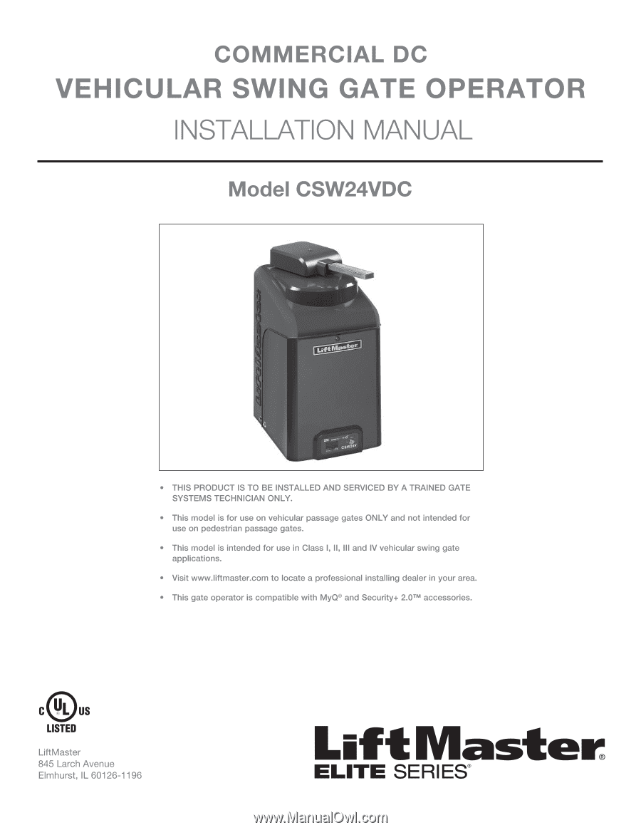
- LiftMaster CSW24VDC | CSW24VDC Installation Manual - Page 1
- LiftMaster CSW24VDC | CSW24VDC Installation Manual - Page 2
34 TROUBLESHOOTING 35 ERROR CODES 35 CONTROL BOARD LEDS 38 TROUBLESHOOTING CHART 39 APPENDIX 42 INSTALLATION TYPES 42 DETERMINE LOCATION FOR CONCRETE PAD AND OPERATOR.........43 CONCRETE PAD AND OPERATOR ATTACHMENT 43 SHORTEN THE OPERATOR ARM 44 POSITION THE GATE BRACKET 44 SOLAR - LiftMaster CSW24VDC | CSW24VDC Installation Manual - Page 3
the gate operator. Failure to adjust and retest the gate operator properly can increase the risk of INJURY or DEATH. • Use the emergency release ONLY when the gate is not moving. • KEEP GATES PROPERLY MAINTAINED. Read the owner's manual. Have a qualified service person make repairs to gate hardware - LiftMaster CSW24VDC | CSW24VDC Installation Manual - Page 4
. Swinging gates shall not open into public access areas. 7. The gate must be properly installed and work freely in both directions prior to the installation of the gate operator. 8. Controls intended for user activation must be located at least 6 feet (1.8 m) away from any moving part of the gate - LiftMaster CSW24VDC | CSW24VDC Installation Manual - Page 5
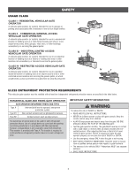
6 feet (1.83 m) above grade. An existing gate latch shall be disabled when a manually operated gate is retrofitted with a powered gate operator. A gate latch shall not be installed on an automatically operated gate. Protrusions shall not be permitted on any gate, refer to ASTM F2200 for Exceptions - LiftMaster CSW24VDC | CSW24VDC Installation Manual - Page 6
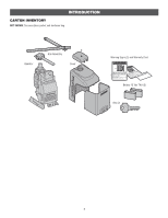
INTRODUCTION CARTON INVENTORY NOT SHOWN: Documentation packet and hardware bag Operator Arm Assembly Cover Warning Signs (2) and Warranty Card Battery 12 Vdc 7AH (2) Key (2) 5 - LiftMaster CSW24VDC | CSW24VDC Installation Manual - Page 7
This model is intended for use in vehicular swing gate applications: Usage Classification Main AC Supply System Operating Voltage Accessory Power Solar Power Max Maximum Gate Weight/Length 90 Degree Travel Time* Maximum Travel Range* Maximum Daily Cycle Rate Maximum Duty Cycle Operating Temperature - LiftMaster CSW24VDC | CSW24VDC Installation Manual - Page 8
CHECK YOUR GATE Gate MUST be level. Gate and gate post MUST be plumb. Gate MUST have a smooth bottom edge, no protrusions should exist. Remove ANY/ALL wheels from the bottom of gate. (Inside Property) Gate MUST NOT hit or drag across ground. Gate MUST swing freely and be supported entirely by - LiftMaster CSW24VDC | CSW24VDC Installation Manual - Page 9
in the back of the manual for more information). SINGLE GATE Warning Sign Photoelectric Sensors Operator Edge Sensors NOTE: One or , trips the sensor while the gate is still moving. Earth Ground Rod Check national and local codes for proper depth DUAL GATE Water Tight Conduit (Not provided) - LiftMaster CSW24VDC | CSW24VDC Installation Manual - Page 10
and outside a horizontal swing gate. Non-contact sensors such as photoelectric sensors MUST be mounted across the gate opening and operate during BOTH the open steps 1-4, pages 43-44. DO NOT run the operator until instructed. The illustration below shows the recommended dimensions for a standard - LiftMaster CSW24VDC | CSW24VDC Installation Manual - Page 11
OPERATOR CHART INSTALLATION Refer to the illustration to determine the measurements and location of the concrete pad. Gate gate and the concrete pad is 32". If this dimension is between 20 and 32 inches, a compact installation is necessary. Refer to Appendix for compact installation instructions - LiftMaster CSW24VDC | CSW24VDC Installation Manual - Page 12
INSTALLATION STEP 2 CONCRETE PAD AND OPERATOR ATTACHMENT CHECK the national and local building codes before installation. NOTE: When lifting the operator use the handle to avoid damaging the operator. 1. Install the electrical conduit. 2. Pour a concrete pad (reinforced concrete is recommended). - LiftMaster CSW24VDC | CSW24VDC Installation Manual - Page 13
slides into the slot. 2. Measure 46 inches along the gate length from the gate hinge center. 3. Measure 27.5 inches up from the concrete pad to the gate hinge position on the gate as shown. 4. Make sure the operator arm is level and tack weld the gate bracket in this position. Use the set screws on - LiftMaster CSW24VDC | CSW24VDC Installation Manual - Page 14
measurements are verified: 1. Weld the gate bracket to the gate. 2. Weld the short arm section. 3. Weld the long arm section. 4. Remove the set screws from the arm. NOTE: Completely weld around the outer tubing and bracket. 5. Adjust the nuts on the operator arm so the operator arm fits snug on the - LiftMaster CSW24VDC | CSW24VDC Installation Manual - Page 15
is not working or loses power or the beam is blocked, then ALL gate operation in that direction will stop. NOTE: Entrapment protection is required for the area between the open gate and the operator. Monitored Photoelectric Sensors (Outside Property) (Inside Property) Sensors for Close Cycle 14 - LiftMaster CSW24VDC | CSW24VDC Installation Manual - Page 16
protection device manual for more information is sensed during gate closing the gate will open to gate opening the gate will reverse for 4 seconds then stop. This input will be disregarded during gate the operator. 2. Run wire from the earth ground rod to the operator. NOTE: If the operator is - LiftMaster CSW24VDC | CSW24VDC Installation Manual - Page 17
secured, at that time the unit may be returned to service. • Disconnect power at the fuse box BEFORE proceeding. Operator MUST be properly grounded and connected in accordance with national and local electrical codes. NOTE: The operator should be on a separate fused line of adequate capacity. • ALL - LiftMaster CSW24VDC | CSW24VDC Installation Manual - Page 18
7AH BATTERIES The batteries are charged in the circuit by the integrated transformer. The batteries are for battery backup. 1. Turn OFF AC power to the operator. 2. Unplug the J15 plug labeled BATT on the control board by squeezing the plug and pulling it from the control board. This disconnects the - LiftMaster CSW24VDC | CSW24VDC Installation Manual - Page 19
or solar installation. The 33AH application requires the 33AH wire harness (Model K94-37236) and an additional battery tray (Model K10-36183 battery as shown. 5. Turn ON AC power to the operator. 6. Turn ON the AC power switch on the operator. 7. Reconnect the J15 plug to the control board. NOTE - LiftMaster CSW24VDC | CSW24VDC Installation Manual - Page 20
standby time than wireless applications. COM LINK B A WIRELESS DUAL GATES TO ACTIVATE THE WIRELESS FEATURE: 1. Choose an operator to be the network primary operator. All wireless accessories will need to be programmed to the primary operator. NOTE: We recommend that all accessories and board - LiftMaster CSW24VDC | CSW24VDC Installation Manual - Page 21
switch is used only with dual gate applications and serves two functions: • BIPART DELAY SWING GATE APPLICATIONS: The BIPART DELAY is used in applications where a mag-lock, solenoid lock, or decorative overlay would require one gate to close before the other. The operator with the LOCK/BIPART DELAY - LiftMaster CSW24VDC | CSW24VDC Installation Manual - Page 22
box. To access the reset switch slide the access door up. The front cover and access door can be locked with the key. 1. Remove the operator arm from the output shaft by releasing the handle. 2. Align the tabs on the rear cover with the slots on the chassis and place the - LiftMaster CSW24VDC | CSW24VDC Installation Manual - Page 23
. ON ON LIMIT SETTING MODE Limits are set. 2 1 INITIAL LIMITS AND FORCE ADJUSTMENT For dual gate applications the limits will have to be set for each operator. The gate MUST be attached to the operator before setting the limits and force. 1. Press and release the SET OPEN and SET CLOSE buttons - LiftMaster CSW24VDC | CSW24VDC Installation Manual - Page 24
an obstruction during motion, the operator will automatically reverse direction of the gate for a short time and then stop 1 the gate. After any adjustments are made, test the operator: 1. Open and close the gate with the test buttons, ensuring that the gate is stopping at the proper open - LiftMaster CSW24VDC | CSW24VDC Installation Manual - Page 25
-Close can be set to close the gate. 1. Press and release the LEARN button (operator will beep and green XMITTER LED will light for a Class B digital device, pursuant to part 15 of the FCC rules. These limits are and used in accordance with the instructions, may cause harmful interference to radio - LiftMaster CSW24VDC | CSW24VDC Installation Manual - Page 26
enters learn mode). The LiftMaster Internet Gateway will pair to the operator if it is within range and the operator will beep if programming is successful. The status as shown by the LiftMaster Internet Gateway app will be either "open" or "closed". The gate operator can then be controlled through - LiftMaster CSW24VDC | CSW24VDC Installation Manual - Page 27
if gate is manually tampered with by being pushed off of close limit. Use during servicing only to Use during servicing only to determine operator cycles. determine operator cycles. Use during servicing only to Use during servicing only to determine operator cycles. determine operator cycles - LiftMaster CSW24VDC | CSW24VDC Installation Manual - Page 28
switch set to CLOSE forces gate to latch at CLOSE limit if Troubleshooting section. 11 Error Code Display: The error code display will show the operator type, firmware version, and error codes. The operator type will display as "SG" followed by a "24" which indicates the operator type as CSW24VDC - LiftMaster CSW24VDC | CSW24VDC Installation Manual - Page 29
/DISCONNECT. Release the handle on the operator arm to allow the gate to be opened and closed manually. On a dual gate application the handle must be released on both operators. To resume normal function tighten the handle by pushing it down. Manual Disconnect Handle RESET SWITCH The reset switch - LiftMaster CSW24VDC | CSW24VDC Installation Manual - Page 30
detector when loop is positioned under the swing of the gate. • Holds open gate at open limit • Only active when the gate is at the OPEN limit, disregarded device sends a pulsed signal to the operator so the operator is aware of the device. If the operator does not receive the signal from the device - LiftMaster CSW24VDC | CSW24VDC Installation Manual - Page 31
within line-of-sight) • STOP and COM: Stops a moving gate. Hard stop (maintained switch overrides Open and Close commands and resets ACCESSORY POWER 24 VDC, MAX 500 mA (4 Terminals) • SWITCHED: Switched ON with gate motion (stays on 5 seconds after motion). • UNSWITCHED: 24 Vdc voltage out to - LiftMaster CSW24VDC | CSW24VDC Installation Manual - Page 32
will remain in present position and operator is powered from batteries. 3 EXIT LOOP FAIL Switch: When set to OPEN, if the EXIT plug-in loop detector (Model LOOPDETLM) detects a fault, then the gate will open and remain open until fault is cleared. When set to CLOSE, then plug-in EXIT loop detector - LiftMaster CSW24VDC | CSW24VDC Installation Manual - Page 33
solar power is present. There is approximately a 10-12 second delay before relay cutoff, after AC shutdown. Energizes when on battery power. There is approximately a 10-12 second delay before relay cutoff, after AC shutdown. Tamper ON OFF ON Energizes if gate is manually gate operator servicing, - LiftMaster CSW24VDC | CSW24VDC Installation Manual - Page 34
. G Shadow Loop Input (2 terminals) Loop wire connection for plug-in loop detector when loop is positioned under the gate. - Holds open gate at open limit - Disregarded during gate motion - Pauses Timer-to-Close at Open Limit H Interrupt Loop Input (2 terminals) Loop wire connection for plug-in - LiftMaster CSW24VDC | CSW24VDC Installation Manual - Page 35
ONLY LiftMaster part 29-NP712 for replacement batteries. • SAVE THESE INSTRUCTIONS. • ALWAYS wear protective gloves and eye protection when changing the battery or working around the battery compartment. MAINTENANCE CHART Disconnect all power (AC, solar, battery) to the operator before servicing - LiftMaster CSW24VDC | CSW24VDC Installation Manual - Page 36
TROUBLESHOOTING To protect against fire and electrocution: • DISCONNECT power (AC or solar and battery) BEFORE installing or servicing operator. For continued protection against fire: • Replace ONLY with fuse of same type and rating. ERROR CODES NOTE: When cycling or disconnecting power (ac/dc) - LiftMaster CSW24VDC | CSW24VDC Installation Manual - Page 37
TROUBLESHOOTING ERROR CODES continued... Some errors are saved in the error code history and some are not. If an error is not saved it will briefly appear on the error code display as it occurs, then disappear. Error Code 31 34 35 36 37 38 40 41 42 43 44 45 46 47 50 53 54 60 61 62 63 64 65 - LiftMaster CSW24VDC | CSW24VDC Installation Manual - Page 38
TROUBLESHOOTING ERROR CODES continued... Some errors are saved in the error code history and some are not. If an error is not saved it will briefly appear on the error code display as it occurs, then disappear. Error Code . If no obstruction, check that the operator arm is engaged and free to move. - LiftMaster CSW24VDC | CSW24VDC Installation Manual - Page 39
blinks per second) GATE OFF MOVING ON The gate is stopped The gate is opening or closing MEDIUM BLINK (1 blink per second) Operator is in E1 (single entrapment) FASTEST BLINK (8 The operator is in E2 (double blinks per second) entrapment) BATT LOW OFF ON No battery error Battery low BLINK - LiftMaster CSW24VDC | CSW24VDC Installation Manual - Page 40
TROUBLESHOOTING CHART SYMPTOM POSSIBLE CAUSES SOLUTIONS Operator does not a) No power to control board a) Check AC and battery power run and error code b) Open fuse b) Check fuses display not on. c) If on battery power only, low or dead batteries c) Charge batteries by AC or solar - LiftMaster CSW24VDC | CSW24VDC Installation Manual - Page 41
to shut off alarm and reset the operator. a) Check if AC power is available. If no AC power, then running on batteries and battery voltage must be 23.0 Vdc or higher. Charge batteries by AC or solar power or replace batteries On dual-gate system, incorrect gate opens first or closes first. Alarm - LiftMaster CSW24VDC | CSW24VDC Installation Manual - Page 42
TROUBLESHOOTING TROUBLESHOOTING CHART c) Old batteries d) Solar panels are not getting enough sunlight Solar operator, insufficient standby time a) more solar panels b) Reduce the accessory power draw by using LiftMaster low power accessories c) Replace batteries d) Relocate the solar panels - LiftMaster CSW24VDC | CSW24VDC Installation Manual - Page 43
installation. APPENDIX (Inside Property) COMPACT INSTALLATION The illustration is an example of a compact installation. If the operator arm will hit an obstruction when the gate is in the open position follow the directions for Compact Installation. (Inside Property) UPHILL DRIVEWAY INSTALLATION - LiftMaster CSW24VDC | CSW24VDC Installation Manual - Page 44
ONLY DO NOT run the operator until instructed. Refer to the illustration to determine the measurements and location of the concrete pad. NOTE: When lifting the operator use the handle to avoid damaging the operator. TOP VIEW OF OPERATOR AND GATE 4" (10.2 cm) maximum Gate Hinge Center NOTE: There - LiftMaster CSW24VDC | CSW24VDC Installation Manual - Page 45
into the slot. 2. Measure 33 inches along the gate length from the gate hinge center. 3. Measure 27.5 inches up from the concrete pad to the gate hinge position on the gate as shown. 4. Make sure the operator arm is level and tack weld the gate bracket in this position. Proceed to Step 5 of - LiftMaster CSW24VDC | CSW24VDC Installation Manual - Page 46
cleaned on a regular basis for best performance to ensure proper operation. SOLAR USAGE GUIDE The CSW24VDC has best in class solar performance due to highly efficient electronics that draw very little power while the gate is not in use (standby). Typical System Standby Battery Current Consumption - LiftMaster CSW24VDC | CSW24VDC Installation Manual - Page 47
1 NOT AVAILABLE 1 BATTERY CURRENT DRAW (mA) 10W SOLAR PANEL 5 15 20 40 60 20W SOLAR PANEL 3 15 20 50 100 40W SOLAR PANEL 5 15 20 100 200 60W SOLAR PANEL 5 15 20 100 250 All numbers are estimates. Actual results may vary. SOLAR GATE CYCLES PER DAY ZONE 1 (6 Hrs sunlight/day - LiftMaster CSW24VDC | CSW24VDC Installation Manual - Page 48
near potential shading or obstructions that will block the panel during any part of the day. • To optimize the system for winter operation the angle can be increased an additional 15° (solar panel(s) sits more vertical). Solar Panel (Facing South) South Operator 180° Sun's Position South 47 - LiftMaster CSW24VDC | CSW24VDC Installation Manual - Page 49
wires up the right side of the operator frame. Connect the red wire to J15 Plug Model K94-37236) 5. Connect the red wire (+) from one solar panel to the black wire (-) of the other solar plug into the board. 40W Solar panel installation Proceed to the Dual Gate section (if applicable) or - LiftMaster CSW24VDC | CSW24VDC Installation Manual - Page 50
Close: ON OFF Bi-Part Delay: OFF (will open first & close last) Tandem Mode: OFF Synchronized Close: ON EXPANSION BOARD Remote Controls Program remote controls 1 to 50 to the primary operator. LiftMaster Program to primary Internet Gateway operator. Garage and Gate Program to primary Monitor - LiftMaster CSW24VDC | CSW24VDC Installation Manual - Page 51
moving arm while setting limits. INITIAL LIMITS AND FORCE ADJUSTMENT For dual gate applications the limits will have to be set for each operator. The gate MUST be attached to the operator before setting the limits and force. Ensure the gate is closed. 1. Press and release the SET OPEN and SET CLOSE - LiftMaster CSW24VDC | CSW24VDC Installation Manual - Page 52
Two 12V Solar Panels in Series + -+ - Accessory Power Outlets Antenna Coaxial Antenna Cable CONTROL BOARD + + + N.C Edge Photoelectric Sensors Photoelectric Sensors COM LINK BA AC & BATT FAIL BACKDRIVE Shielded Twisted Pair Cable Primary/Secondary link to other gate operator Ground the - LiftMaster CSW24VDC | CSW24VDC Installation Manual - Page 53
REPAIR PARTS INDIVIDUAL PARTS ITEM 1 2 PART NUMBER K13-36117-1 K77-37181 3 K73-36109 4 K76-34644 5 K19-50038 24 Q118 25 K13-34729 26 Q061 27 Q059 28 Q060 29 Q104 DESCRIPTION Cludge Cover Operator Cover with labels, keys, and lock assembly Chassis APS Encoder with cable #50 Drive - LiftMaster CSW24VDC | CSW24VDC Installation Manual - Page 54
12 7 5 REPAIR PARTS 1 28 9 6 19 26 27 8 29 22 10 11 20 3 4 18 13 14 21 15 23 24 53 17 16 25 2 - LiftMaster CSW24VDC | CSW24VDC Installation Manual - Page 55
Enables homeowner to operate gate operator from outside by entering a 4-digit code on a specially designed keypad. Model 877MAX MISCELLANEOUS POST-MOUNTING PLATE For post-mounting model CSW24VDC commercial swing operator (also CSW200 commercial swing operator). Posts not included. Model MPEL REMOTE - LiftMaster CSW24VDC | CSW24VDC Installation Manual - Page 56
batteries within a gate operator. 7AH BATTERIES Standard 7 AMP-Hour Battery, 12 Vdc, to replace original batteries provided with operator. Reuse existing harnesses. Models 29-NP712 (1) and K74-30762 (2) 33AH BATTERIES Upgrade 33 AMP-Hour Battery, 12 Vdc. Ideal for solar applications and extended
-
 1
1 -
 2
2 -
 3
3 -
 4
4 -
 5
5 -
 6
6 -
 7
7 -
8
-
9
-
10
-
11
-
12
-
13
-
14
-
15
-
16
-
17
-
18
-
19
-
20
-
21
-
22
-
23
-
24
-
25
-
26
-
27
-
28
-
29
-
30
-
31
-
32
-
33
-
34
-
35
-
36
-
37
-
38
-
39
-
40
-
41
-
42
-
43
-
44
-
45
-
46
-
47
-
48
-
49
-
50
-
51
-
52
-
53
-
54
-
55
-
56
 |
 |