LiftMaster CSW24VDC CSW24VDC Installation Manual - Page 11
Step 1 Continued..., Determine Location For Concrete Pad And Operator
 |
View all LiftMaster CSW24VDC manuals
Add to My Manuals
Save this manual to your list of manuals |
Page 11 highlights
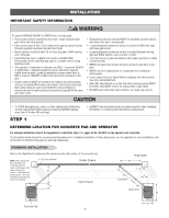
INSTALLATION STEP 1 continued... DETERMINE LOCATION FOR CONCRETE PAD AND OPERATOR CHART INSTALLATION Refer to the illustration to determine the measurements and location of the concrete pad. Gate Hinge Center OUT A 4" (10.2 cm) maximum OUT NOTE: There should only be a maximum of 4" (10.2 cm) IN from the center of the hinge IN to the edge of the post or column. If the distance is B E greater than 4" (10.2 cm) entrapment protection for this Long Arm area is required. C Short Arm D D MINUS 10" 10" DISTANCE DISTANCE Wall Concrete Pad DISTANCE Dimension (A) thru (E) are from the center of one pivot point to the center of another pivot point. Caution: If the gate is longer than 18 feet, follow CHART A: A-2. Suggestion: The dimensions between the gate and the concrete pad is always 10 inches less than the dimension D. Example: D = 42", if the dimensions between the gate and the concrete pad is 32". If this dimension is between 20 and 32 inches, a compact installation is necessary. Refer to Appendix for compact installation instructions. CHART A ABCDE CHART B ABCDE 1 46" 35.5" 29.5" 35" 11" 45" 1 34.5" 34.75" 29.5" 35" 14" 43" 2 46.75" 35.5" 33.5" 42" 11" 37" 2 44" 36.5" 32.5" 42" 14" 32" 3 46.75" 37" 31.5" 40" 11" 41" 3 44" 37" 30.5" 40" 14" 40" 4 47.25" 37.25" 30" 37" 11" 45" 4 45" 37" 30.5" 37" 14" 43" 5 47" 35" 29.5" 32" 11" 45" 5 44.75" 35.75" 29.5" 32" 14" 44" 6 42.5" 33" 26.5" 28.5" 11" 41" 6 41" 39" 27.5" 28.5" 14" 41" 10
-
 1
1 -
2
-
3
-
4
-
5
-
 6
6 -
 7
7 -
 8
8 -
 9
9 -
 10
10 -
 11
11 -
 12
12 -
 13
13 -
 14
14 -
 15
15 -
 16
16 -
17
-
18
-
19
-
20
-
21
-
22
-
23
-
24
-
25
-
26
-
27
-
28
-
29
-
30
-
31
-
32
-
33
-
34
-
35
-
36
-
37
-
38
-
39
-
40
-
41
-
42
-
43
-
44
-
45
-
46
-
47
-
48
-
49
-
50
-
51
-
52
-
53
-
54
-
55
-
56
 |
 |
