LiftMaster CSW24VDC CSW24VDC Installation Manual - Page 14
Step 5 Secure The Operator Arm
 |
View all LiftMaster CSW24VDC manuals
Add to My Manuals
Save this manual to your list of manuals |
Page 14 highlights
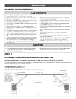
INSTALLATION STEP 5 SECURE THE OPERATOR ARM Once the operator arm measurements are verified: 1. Weld the gate bracket to the gate. 2. Weld the short arm section. 3. Weld the long arm section. 4. Remove the set screws from the arm. NOTE: Completely weld around the outer tubing and bracket. 5. Adjust the nuts on the operator arm so the operator arm fits snug on the output shaft yet still allows enough room to swivel (the handle must be in a 90° position). 6. Tighten the handle by pushing it down. Test to make sure the operator arm does not slip on the output shaft. 7. Remove the pin from the vent plug on both the top and bottom gear boxes. Top Gear Box Bottom Gear Box 13 Pin Vent Plug
-
 1
1 -
2
-
3
-
4
-
5
-
6
-
7
-
8
-
 9
9 -
 10
10 -
 11
11 -
 12
12 -
 13
13 -
 14
14 -
 15
15 -
 16
16 -
 17
17 -
 18
18 -
 19
19 -
20
-
21
-
22
-
23
-
24
-
25
-
26
-
27
-
28
-
29
-
30
-
31
-
32
-
33
-
34
-
35
-
36
-
37
-
38
-
39
-
40
-
41
-
42
-
43
-
44
-
45
-
46
-
47
-
48
-
49
-
50
-
51
-
52
-
53
-
54
-
55
-
56
 |
 |

13
STEP 5
SECURE THE OPERATOR ARM
Once the operator arm measurements are verified:
1. Weld the gate bracket to the gate.
2. Weld the short arm section.
3. Weld the long arm section.
4.
Remove the set screws from the arm.
NOTE:
Completely weld around
the outer tubing and bracket.
5.
Adjust the nuts on the operator arm so the operator arm fits snug on
the output shaft yet still allows enough room to swivel (the handle
must be in a 90° position).
6.
Tighten the handle by pushing it down. Test to make sure the operator
arm does not slip on the output shaft.
7.
Remove the pin from the vent plug on both the top and bottom gear
boxes.
Pin
Top Gear Box
Bottom Gear Box
Vent Plug
INSTALLATION