LiftMaster LA400 LA400 Manual
LiftMaster LA400 Manual
 |
UPC - 753182403953
View all LiftMaster LA400 manuals
Add to My Manuals
Save this manual to your list of manuals |
LiftMaster LA400 manual content summary:
- LiftMaster LA400 | LA400 Manual - Page 1
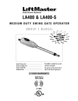
LA400 & LA400-S MEDIUM DUTY SWING GATE OPERATOR OWNER'S MANUAL MeBtOoLaaxplrtC(giXooennLMatrl)ol Serial # Primary Arm Serial # Secondary Arm Serial # Control Box Installation Date The LA400 is intended for use with vehicular swing gates. The operator can be used in Class I, Class II and Class III - LiftMaster LA400 | LA400 Manual - Page 2
Button Remote Control Manual Release Maintenance TROUBLESHOOTING Basic Control Board Layout Wiring Diagram Diagnostic Codes Troubleshooting Chart REPAIR PARTS Control Box Gate Operator Arm How to Order Repair Parts WARRANTY POLICY ACCESSORIES TEMPLATE SAFETY » SAFETY SYMBOL AND SIGNAL WORD REVIEW - LiftMaster LA400 | LA400 Manual - Page 3
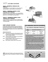
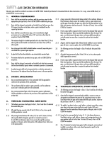
intended to service the general public. SAFETY ACCESSORY SELECTION All UL325 compliant LiftMaster gate operators will accept PROTECTION REQUIREMENTS GATE OPERATOR ENTRAPMENT PROTECTION UL325 Installation CLASS CLASS I CLASS II CLASS III Swing & Gate Barrier (Arm) Operator Primary Type - LiftMaster LA400 | LA400 Manual - Page 4
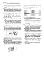
. Swinging gates shall not open into public access areas. 7. The gate must be properly installed and work freely in both directions prior to the installation of the gate operator. 8. Controls intended for user activation must be located at least 6 feet (1.83 m) away from any moving part of the gate - LiftMaster LA400 | LA400 Manual - Page 5
for panel types. 1.5 An existing gate latch shall be disabled when a manually operated gate is retrofitted with a powered gate operator. 3.2 The following provisions shall apply to Class IV vehicular horizontal slide gates: 1.6 A gate latch shall not be installed on an automatically operated gate - LiftMaster LA400 | LA400 Manual - Page 6
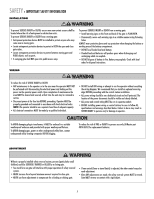
use only LiftMaster part #K74-30762 for replacement batteries. ADJUSTMENT Without a properly installed safety reversal system, persons (particularly small children) could be SERIOUSLY INJURED or KILLED by a closing gate. • Too much force on gate will interfere with proper operation of safety - LiftMaster LA400 | LA400 Manual - Page 7
. • SAVE THESE INSTRUCTIONS. To reduce the risk of FIRE or INJURY to persons use only LiftMaster part #K74-30762 for replacement batteries. To avoid SERIOUS personal INJURY or DEATH from electrocution, DISCONNECT electrical power to operator BEFORE proceeding. TROUBLESHOOTING To protect against - LiftMaster LA400 | LA400 Manual - Page 8
(Gate 2) installation the carton inventory is doubled except for control box. • Standard Control Box (1) • Hardware Bag (1) • Gate Operator Arm • Motor Cable - Six Conductor, 9 feet (2.7 m) • Warning Sign (2) • Battery (2) • Plug-in Transformer (1) LA400-S (SECOND GATE OPERATOR ARM) • Motor - LiftMaster LA400 | LA400 Manual - Page 9
INSTALLATION + TOOLS NEEDED ADDITIONAL ITEMS NEEDED FOR INSTALLATION PERMANENT FASTENERS FOR WARNING SIGN EARTH GROUND ROD (OPTIONAL) POWER WIRE: 120 VAC POWER (305 m) TOOLS NEEDED During assembly, installation and adjustment of the operator, instructions will call for tools as illustrated below - LiftMaster LA400 | LA400 Manual - Page 10
» OVERVIEW OF TYPICAL INSTALLATION LEFT-HAND GATE Warning Sign Antenna Control Box with Batteries Hinge Post Bracket Gate Bracket PVC Conduit (not provided) to protect the low voltage wire from lawn mowers and string trimmers. Operator Operator Cable Earth Ground Installation (Optional) 12 - LiftMaster LA400 | LA400 Manual - Page 11
» OVERVIEW OF TYPICAL INSTALLATION DUAL GATE Warning Sign Hinge Antenna Post Bracket Gate Bracket Gate 1 Control Box with Batteries Operator Cable Gate 2 Junction Box Extension Cable Photoelectric Sensors PVC Conduit (not provided) to protect the low voltage wire from lawn mowers - LiftMaster LA400 | LA400 Manual - Page 12
C D Gate MUST swing freely and be supported entirely by its hinges. D MOUNTING OPTIONS Mounting locations vary depending on type and style of your gate. Minimum distance from the ground should not be less than 4 inches (10.2 cm) from the bottom of the gate operator arm. RECOMMENDED: = Gate post - LiftMaster LA400 | LA400 Manual - Page 13
key into the lock and turn it 180° counterclockwise. 2 Turn the release lever 180° counterclockwise. The operator is now in manual mode. Key 1 2 DETERMINE POSITION OF THE PULL-TO-OPEN BRACKET The Pull-to-Open bracket can be assembled to work on a Left-Hand or a Right-Hand gate. 1 Review the gate - LiftMaster LA400 | LA400 Manual - Page 14
Gate installation. For Push-to-Open installations refer to instructions with Push-to-Open kit 50-19503. ASSEMBLE GATE POST BRACKET (PULL-TO-OPEN) 1 Assemble gate post bracket by placing Pull-to-Open bracket on top of post bracket. 2 Insert the bolt through both brackets and secure with washer, lock - LiftMaster LA400 | LA400 Manual - Page 15
dimensions for the Pull-to-Open bracket. NOTE: It may be necessary to add shims (angle iron, sheets of metal or wood) to the gate post to achieve the required dimensions. Gate Post Gate Hinge Point Gate Post Gate Hinge Point Gate Post Gate Hinge Point Operator Hinge Point 7" (18 cm) 7" (18 - LiftMaster LA400 | LA400 Manual - Page 16
INSTALLATION » POSITION GATE OPERATOR ON GATE POSITION GATE OPERATOR ON GATE NOTE: The post bracket assembly can be mounted several places on the gate post. Refer to page 11 for mounting options. 1 Open the gate to desired open position (no greater than 100°) and hold operator against gate. 2 - LiftMaster LA400 | LA400 Manual - Page 17
INSTALLATION » TEST GATE TRAVEL + SECURE POST BRACKET TO GATE POST TEST GATE TRAVEL NOTE: If gate does not open and close completely adjust the position of the 1 gate bracket and mark new mounting holes. 1 Manually open and close the gate. 2 Ensure that the operator does not bind against the - LiftMaster LA400 | LA400 Manual - Page 18
3 Manually move the gate to verify that it opens and closes fully. Reinforcement Area 1 Operator Angle Iron OR Wood OR Flat Bar Welder (Optional) Hex Nut Lock Washer Flat Washer 2 Gate Bracket Hex Bolt 3 WARNING SIGN PLACEMENT Warning signs MUST be installed on both sides of the gate and - LiftMaster LA400 | LA400 Manual - Page 19
BOX The control box MUST be mounted within 5 feet (1.5 m) of the gate operator. Mount the control box as high as possible for best radio reception. 1 Remove screws and open the control box. 1 2 Disconnect the reset button, alarm, and coaxial connector. 3 Loosen screws to remove the control board - LiftMaster LA400 | LA400 Manual - Page 20
INSTALLATION » STANDARD CONTROL BOX INSTALL THE CONTROL BOARD NOTE: Make sure the battery leads are on the left side of the control box and not pinched. 1 Attach the antenna. 2 Reinstall the batteries, control board, alarm and reset button. 1 2 Coaxial Connector Reset Button Connections Alarm 19 - LiftMaster LA400 | LA400 Manual - Page 21
TIMER TO CLOSE OPEN CONTROL INPUTS SINGLE BUTTON RESET OFF MAX STOP CTRL PWR CTRL PWR SHADOW LOOP INPUTS INTERRUPT CHGR OVLD CTRL PWR AC PWR /SOLAR ALARM LOCK SOL GND MAGR GATE 1 BR GR WH YL BL RD ACCESSORY POWER 12 V BR GR WH YL BL RD GATE 2 ALARM LOCK SOL GND MAGR GATE 1 BR GR - LiftMaster LA400 | LA400 Manual - Page 22
two 7AH batteries, purchased separately. See Accessories page. IMPORTANT NOTE: There are two receptacles located inside the control box. One of the receptacles is for the control board power supply. The second receptacle can be used to power up additional gate operator accessories. ALARM LOCK SOL - LiftMaster LA400 | LA400 Manual - Page 23
the control box. 4 Extend the operator cable and wires to the Gate 1 connector and connect as shown. 5 Tighten watertight connector nut. NC 4 Z1 GATE 1 10A 32V BRN D1Ø GRN WHT YEL BLU RED Z12 ACCESSORY POWER GATE 1 BRN GRN WHT U4 YEL BLU RED 3 MAX C13 C4 F6 F2 FUSE OPEN Nut - LiftMaster LA400 | LA400 Manual - Page 24
In some dual gate installations, one gate will need to open first and close second. This would happen if there was an ornamental overhang on one gate or if using a solenoid lock, for example. This gate is called the Primary gate and needs to be connected to Gate 1 connections on the control board - LiftMaster LA400 | LA400 Manual - Page 25
WIRING » CONNECT THE GATE OPERATOR (GATE 2) TO THE CONTROL BOX (MODEL LA400-S ONLY) CONNECT THE GATE OPERATOR (GATE 2) TO THE CONTROL BOX (MODEL LA400-S ONLY) Before digging, contact local underground utility locating companies. 1 Trench across driveway to bury the extension cable. Use PVC conduit - LiftMaster LA400 | LA400 Manual - Page 26
WIRING » JUNCTION BOX (MODEL LA400-S ONLY) JUNCTION BOX The following items are required to complete the junction box installation: • 4 x 4 Junction Box with 3/4" NPT threaded port holes • Screws • PVC Conduit 1 1 Open the junction box by removing screws (4) and set aside. 2 Select holes to - LiftMaster LA400 | LA400 Manual - Page 27
WIRING » JUNCTION BOX (MODEL LA400-S ONLY) 7 Insert wires from extension cable and operator cable into terminal block connector. 7 OpOeprearattoorrCCabaleble SpeTecrmiainlal Block ConnCoencnetcotorr BBrroowwn n GGrreeeenn WWhhiittee YYeellllooww BBluluee RReedd BBrroowwn n GGrreeeenn WWhhiittee - LiftMaster LA400 | LA400 Manual - Page 28
TO CONTROL BOARD NOTE: All power wiring should be on a dedicated circuit, calculated using NEC guidelines. Local codes and conditions must be reviewed for suitability of wire installation. EXTERNAL RECEPTACLE 1 The transformer can be plugged into a receptacle external to the control box. 2 Run - LiftMaster LA400 | LA400 Manual - Page 29
Z1 GATE 1 ACCESSORY POWER GATE 2 R4 J4 FUSE FUOSPEEN OPEN D15 C2 MOV2 Control Box R4 C2 J4 24 VAC/ SOLAR INPUT Ground Screw 12 Gauge Wire 3' (0.9 m) Earth Ground Installation (Optional) 8' (2.4 m) CONNECT BATTERIES The batteries are the main source of power for the operator. The operator - LiftMaster LA400 | LA400 Manual - Page 30
in order for the changes to be saved. 1 Set the Save switch to the OFF position. 1 2 Set switch to Single for single gate installation. For Dual (Gate 1 and 2) installation set switch on Dual Mode. 3 Set the Save switch to the ON position. 2 OFF OFF SINGLE NO NO OFF OFF SINGLE NO NO 3 OFF OFF - LiftMaster LA400 | LA400 Manual - Page 31
the RESET button on the outside of the control box to start over. The programming times-out automatically after 60 seconds of inactivity. 1 Close the gate. 2 Engage the operator by turning the release lever clockwise 180°, then turning the key clockwise 180°. SINGLE ARM LEFT-HAND SIDE PROGRAM OPEN - LiftMaster LA400 | LA400 Manual - Page 32
1 left button to close the left operator. DIAGNOSTIC GATE 1 SET CLOSE 9 Press the LEARN LIMITS button. SET OPEN LIMIT SET CLOSE LIMIT The control board beeps and the SET OPEN LIMIT and SET CLOSE LIMIT LEDs stop blinking, programming is now complete. (If the SET OPEN LIMIT LED continues to blink - LiftMaster LA400 | LA400 Manual - Page 33
SET GATE 1 button. OPEN LIMIT SET CLOSE LIMIT FORCE SET CLOSE The control board beeps and the SET OPEN LIMIT and SET CLOSE LIMIT LEDs stop blinking, programming is now complete. (If the SET OPEN LIMIT LED continues to blink, repeat programming. If the problem continues, see Troubleshooting - LiftMaster LA400 | LA400 Manual - Page 34
or the Single Button Control (SBC) button on the control board, open and then close the gate. 2 If the gate stops or reverses before reaching the fully open or closed position increase the force by turning the force control slightly. FORCE D4 D2 FORCE 2 OFF MAX 3 Run operator through a complete - LiftMaster LA400 | LA400 Manual - Page 35
PIN can be programmed to the operator. For highest level of security, we recommend the Security✚® line of products. Refer to Accessories. TO ADD OR REPROGRAM A REMOTE CONTROL (NOT PROVIDED) 1 Remote Control LEARN XMITTER Button 1 Press LEARN XMITTER button and release (LED will light up). LEARN - LiftMaster LA400 | LA400 Manual - Page 36
-2) enables the Maglock feature. On an open command there will be a 1/2 second delay before the motor starts, to allow the Maglock to release. C MODE DUAL/SINGLE This switch (S1-3) sets the mode as Dual or Single (Refer to page 29). D SAFETY INPUTS Swing gates allow four safety inputs. A DIP switch - LiftMaster LA400 | LA400 Manual - Page 37
only if remotely mounted Stop button is added. OPEN Opens only or reverses a closing gate. SBC (SINGLE BUTTON CONTROL) INPUT C2 This input will command the gate to OPEN / STOP / CLOSE / STOP in sequence. RESET CONTROL INPUT The control box has a factory installed internal reset button. These - LiftMaster LA400 | LA400 Manual - Page 38
instructions for connections. PHOTO/EDGE INPUTS (P6-7-8 AND 9) TERMINAL P6 - CLOSE SAFETY EDGE This input will reverse a closing gate. It will disable the Timer-to-Close if that feature has been enabled. Activating this input while the gate is opening will have no effect. Order part number LA400 - LiftMaster LA400 | LA400 Manual - Page 39
R1 XMITTER SINGLE NO DUAL MODE NC EDGE 2 F3 NO NC PHOTO S1 K2 DIAGNOSTIC GATE 1 K1 Q9 SET OPEN LIMIT SET CLOSE LIMIT LEARN LIMITS R2Ø7 Z2Ø R227 J18 U4 R224 Z22 R92 R91 R94 R93 CLOSE EDGE OPEN EDGE/ PHOTO Z9 OPEN PHOTO Z8 CLOSE PHOTO 24V ACCESSORY R9Ø POWER 24V R1Ø1 FORCE - LiftMaster LA400 | LA400 Manual - Page 40
of the remote control button will close the gate. MANUAL RELEASE In case of a power failure, the operator can be disengaged from the gate. With an operator, the release action may sometimes feel stiff/jerky, which is normal and has 1 no effect on function. RELEASE 1 Insert the key into the lock - LiftMaster LA400 | LA400 Manual - Page 41
» MAINTENANCE MAINTENANCE Disconnect power before servicing. DESCRIPTION External Entrapment Protection System Manual Release Gate Accessories Electrical Mounting Hardware Batteries Operator Warning Signs TASK Check and test for proper operation Check and test for proper operation Inspect for wear - LiftMaster LA400 | LA400 Manual - Page 42
Connector P16 11 Connector P13 12 Connector P17 13 Connector P14 FUNCTION Antenna Input Close Edge Open Edge/Photo Open Photo Close Photo Switched Accessory Power* Control Inputs Loop Inputs 24 Vac Input Gate 2 Accessory Power* Gate 1 Maglock/Solenoid *See page 38 for max current draw ITEM - LiftMaster LA400 | LA400 Manual - Page 43
is installed. 16 15 NOTE: Batteries must be connected to operate. # OF BLINKS 1 2 3 4 5 DIAGNOSTIC CODES MEANING No Stop Switch Connected Gate 1 Arm Disengaged Gate 2 Arm Disengaged Both Gate Arms Disengaged RPM Reversal # OF BLINKS 6 7 8 9 10 42 MEANING Force Reversal Processor Reset ROM - LiftMaster LA400 | LA400 Manual - Page 44
batteries. Replace motor. Replace control board. Clear gate from obstruction. See Force Adjustment section. Service/replace gate hardware. See Installation section of operator arm. Check for obstruction on arm, verify arm is not bottomed out. Replace arm. Move accessories to separate power source - LiftMaster LA400 | LA400 Manual - Page 45
1 Control Board Bracket 1 Reset Switch 1 Antenna 1 Battery 2 Transformer 1 Alarm 1 Not Shown ATC Fuse Kit Includes 20 Amp (1), 15 Amp (2) Receiver Module - 390 MHz Receiver Module - 315 MHz Reset Switch (XLM Control Box) Alarm (XLM Control Box) GATE OPERATOR ARM 22 33 ITEM PART - LiftMaster LA400 | LA400 Manual - Page 46
INSTALLATION AND SERVICE INFORMATION, CALL OUR TOLL FREE NUMBER 1-800-528-2806 www.liftmaster.com WHEN ORDERING REPAIR PARTS PLEASE SUPPLY THE FOLLOWING INFORMATION: PART NUMBER DESCRIPTION MODEL NUMBER ADDRESS ORDER TO: THE CHAMBERLAIN GROUP, INC. Technical Support CONNECTION WITH THE SALE OF THIS - LiftMaster LA400 | LA400 Manual - Page 47
be released in case of an emergency. Requires separate power supply (Model ARMP5). Magnetic Gate Lock: Outdoor magnetic lock, transformer, junction box, mounting plate and hardware. 373LM 86LM 377LM 3-Button SECURITY✚®OPENRemote Control : Includes visor clip. 29-NP712 Remote Antenna Mounting Kit - LiftMaster LA400 | LA400 Manual - Page 48
TEMPLATE FOR POST BRACKET MOUNTING 7 6 5 4 3 2 1 7 6 5 4 3 2 1 01-19244H © 2010, The Chamberlain Group, Inc. All Rights Reserved
-
 1
1 -
 2
2 -
 3
3 -
 4
4 -
 5
5 -
 6
6 -
 7
7 -
8
-
9
-
10
-
11
-
12
-
13
-
14
-
15
-
16
-
17
-
18
-
19
-
20
-
21
-
22
-
23
-
24
-
25
-
26
-
27
-
28
-
29
-
30
-
31
-
32
-
33
-
34
-
35
-
36
-
37
-
38
-
39
-
40
-
41
-
42
-
43
-
44
-
45
-
46
-
47
-
48
 |
 |
LA400 & LA400-S
MEDIUM DUTY SWING GATE OPERATOR
O
W N E R ' S
M A N U A L
Serial # Primary Arm
Serial # Secondary Arm
Serial # Control Box
Installation Date
2 YEAR WARRANTY
Radio Receiver
Built on Board
315 MHz
The LA400 is intended for use with
vehicular swing gates.
The operator can be used in Class I,
Class II and Class III applications.
Large
Metal Control
Box (XLM)
Optional