LiftMaster LA400 LA400 Manual - Page 39
» Safety Accessories For Secondary Entrapment Protection - solenoid lock
 |
UPC - 753182403953
View all LiftMaster LA400 manuals
Add to My Manuals
Save this manual to your list of manuals |
Page 39 highlights
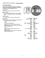
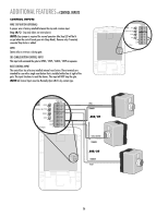
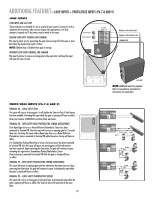
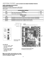
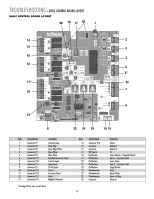
ADDITIONAL FEATURES » SAFETY ACCESSORIES FOR SECONDARY ENTRAPMENT PROTECTION SAFETY ACCESSORIES FOR SECONDARY ENTRAPMENT PROTECTION The following devices are acceptable for Safety Accessories for secondary entrapment protection. These devices have been tested with the LA400 to meet the requirements of UL325 and UL991. MODEL CPS-LN4 CPS-RN4 MODEL G65MG0204 G65MG0205 G65MGR205 G65MGS205 PHOTOELECTRIC CONTROLS DESCRIPTION Emitter, receiver and mounting brackets - 30 feet (9 m) Ranges VOLTAGE +24 Vdc Emitter with reflector and mounting brackets +24 Vdc SENSING EDGES DESCRIPTION Miller MG020 2-wire electric edge for gates. Sensitized on three sides. (Requires mounting channel. PIN:G65ME120C5) Miller MG020 2-wire electric edge for gates. Sensitized on three sides. (Requires mounting channel. PIN:G65ME120C5) Miller MGR20 2-wire electric edge in 5 feet (1.5 m) lengths for 2 inch (5 cm) round post. Miller MGR20 2-wire electric edge in 5 feet (1.5 m) lengths for 2 inch (5 cm) square post. Solenoid Lock (optional) MAGLOCK NO C NC ACCESSORY POWER 24V Maglock (optional) MAGLOCK NO C NC (not provided) Flashing Strobe (optional) Siren (optional) Fault Alarm Provides 24 Vdc. Do not exceed 500mA with 115 Vac power supply or 300mA with 24 Vac power supply. MAX CURRENT DRAW: • 115 Vac power to control box - 500 mA accessory power, 150 mA switched accessory power. • 24 V power to control box depending on wire gauge and distance - 300 mA accessory power, 75 mA switched accessory power. P1 D6 O1 2 3 4 5 N MAGLOCK When enabled, the Maglock output is activated (energized) while the gate is in motion. P2 R223 ALARM NO C MAGLOCK NO C NC Z1 GATE 1 BRN GRN WHT YEL BLU RED 10A 32V D1Ø Z12 J19 K6 Ø14GPØ89ØE Ø14LGØ89ØE Ø14SKØ89ØE J 1 K5 L1 1 S8 R2 OFF OFF ON SAVE ON MAGLOCK LEARN R1 XMITTER SINGLE NO DUAL MODE NC EDGE 2 F3 NO NC PHOTO S1 K2 DIAGNOSTIC GATE 1 K1 Q9 SET OPEN LIMIT SET CLOSE LIMIT LEARN LIMITS R2Ø7 Z2Ø R227 J18 U4 R224 Z22 R92 R91 R94 R93 CLOSE EDGE OPEN EDGE/ PHOTO Z9 OPEN PHOTO Z8 CLOSE PHOTO 24V ACCESSORY R9Ø POWER 24V R1Ø1 FORCE GATE 2 TIMER RUNNING BIPART DELAY TIMER TO SINGLE CLOSE BUTTON COM OVLD OVLD OPEN SWITCHED ACCESSORY POWER CONTROL INPUTS GATE 2 BRN GRN WHT YEL BLU RED 10A 32V R4 C2 J4 D15 R196 24 VAC/ SOLAR INPUT MOV2 R1ØØ F4 ACCESSORY OVLD K4 F5 D21 K3 D8 Q22 D22 MIN MAX OFF MAX R35 D9 C12 D27 Z3 Z4 U3 C11 OFF MAX F7 C13 C4 F6 F2 SINGLE BUTTON RESET STOP POWER COM COM SHADOW LOOP INPUTS INTERRUPT CHGR OVLD COM F1 20A 32V MOV1 JMPR2 DB1 C64 U2 R9 D1 JMPR1 D4 D2 FUSE OPEN BATT 2 BATT 1 Accessory Power AUXILIARY OUTPUT POWER FOR OPTIONAL DEVICES (2) +24 Vdc Outputs have been provided for optional devices Make sure the rubber seal around the cover is intact and close the cover. Secure the control box cover with screws (4). Installation is complete. 38
-
 1
1 -
2
-
3
-
4
-
5
-
6
-
7
-
8
-
9
-
10
-
11
-
12
-
13
-
14
-
15
-
16
-
17
-
18
-
19
-
20
-
21
-
22
-
23
-
24
-
25
-
26
-
27
-
28
-
29
-
30
-
31
-
32
-
33
-
 34
34 -
 35
35 -
 36
36 -
 37
37 -
 38
38 -
 39
39 -
 40
40 -
 41
41 -
 42
42 -
 43
43 -
 44
44 -
45
-
46
-
47
-
48
 |
 |
