LiftMaster LA400 LA400 Manual - Page 19
» Standard Control Box - control board
 |
UPC - 753182403953
View all LiftMaster LA400 manuals
Add to My Manuals
Save this manual to your list of manuals |
Page 19 highlights
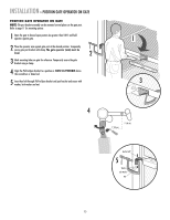
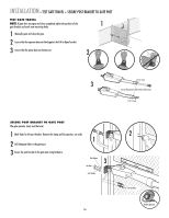
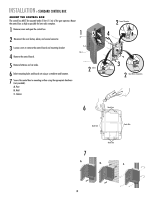
INSTALLATION » STANDARD CONTROL BOX MOUNT THE CONTROL BOX The control box MUST be mounted within 5 feet (1.5 m) of the gate operator. Mount the control box as high as possible for best radio reception. 1 Remove screws and open the control box. 1 2 Disconnect the reset button, alarm, and coaxial connector. 3 Loosen screws to remove the control board and mounting bracket. 4 Remove the control board. 5 Remove batteries and set aside. 6 Select mounting holes and knock out using a screwdriver and hammer. 7 Secure the control box to mounting surface using the appropriate hardware (not provided). A. Post B. Wall C. Column 5 2 Alarm 6 2 Coaxial Connector 4 3 2 Reset Button Connections Knock Outs Knock Outs Knock Outs 7 A. Knock Outs B. C. 18
-
 1
1 -
2
-
3
-
4
-
5
-
6
-
7
-
8
-
9
-
10
-
11
-
12
-
13
-
 14
14 -
 15
15 -
 16
16 -
 17
17 -
 18
18 -
 19
19 -
 20
20 -
 21
21 -
 22
22 -
 23
23 -
 24
24 -
25
-
26
-
27
-
28
-
29
-
30
-
31
-
32
-
33
-
34
-
35
-
36
-
37
-
38
-
39
-
40
-
41
-
42
-
43
-
44
-
45
-
46
-
47
-
48
 |
 |
18
Knock Outs
Knock Outs
Knock Outs
Knock Outs
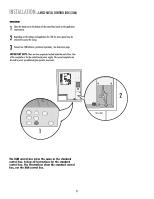
MOUNT THE CONTROL BOX
The control box MUST be mounted within 5 feet (1.5 m) of the gate operator. Mount
the control box as high as possible for best radio reception.
Remove the control board.
Remove batteries and set aside.
Disconnect the reset button, alarm, and coaxial connector.
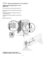
Select mounting holes and knock out using a screwdriver and hammer.
Remove screws and open the control box.
Loosen screws to remove the control board and mounting bracket.
1
3
4
5
2
6
INSTALLATION
» STANDARD CONTROL BOX
7
A.
B.
C.
7
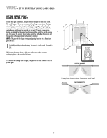
Secure the control box to mounting surface using the appropriate hardware
(not provided).
A.
Post
B.
Wall
C.
Column
6
Coaxial Connector
Reset Button Connections
Alarm
2
2
2
1
3
4
5