LiftMaster LA400 LA400 Manual - Page 36
Additional, Features - chamberlain
 |
UPC - 753182403953
View all LiftMaster LA400 manuals
Add to My Manuals
Save this manual to your list of manuals |
Page 36 highlights
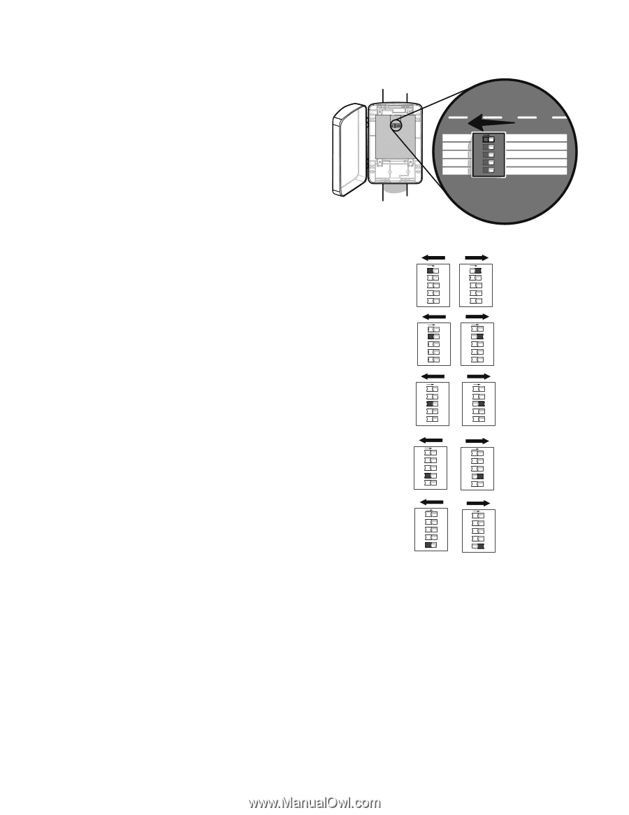
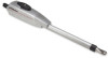
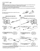
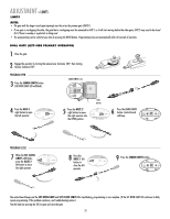
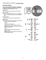
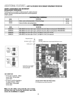
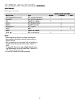
ADDITIONAL FEATURES » DIP SWITCH SETTINGS DIP SWITCH SETTINGS The Save switch must be in the OFF position prior to adjusting the switches. After the adjustments are made the Save switch must be in the ON position in order for the changes to be saved. A SAVE SWITCH S1-1 This switch (S1-1) is used to save the settings for switches 2 through 5. B MAG DELAY ENABLE This switch (S1-2) enables the Maglock feature. On an open command there will be a 1/2 second delay before the motor starts, to allow the Maglock to release. C MODE DUAL/SINGLE This switch (S1-3) sets the mode as Dual or Single (Refer to page 29). D SAFETY INPUTS Swing gates allow four safety inputs. A DIP switch is required for determining between N/O and N/C edges and N/O and N/C eyes. EDGE INPUT Set switch (S1-4) to the following settings: N/O Edge (Active Close) = N/O dry contact edge or monitored edge NOTE: Monitored Edges should be set in the N/O position, as the activation condition is shorting the terminals. EYE INPUT This switch (S1-5) differentiates between N/O and N/C dry contact photoelectric eye inputs. NOTE: Pulsing Chamberlain (CPS-L) photoelectric eyes will automatically learn in N/O mode (See Accessories). OFF OFF SINGLE NO NO ON SAVE ON MAGLOCK DUAL MODE NC EDGE NC PHOTO S1 A SAVE OFF B OFF MAGLOCK OFF OFF C OFF SINGLE NO NO OFF OFF EDGE NO D OFF OFF PHOTO NO O1 2 3 5 N O1 2 3 4 N O1 2 3 4 5 N O1 2 3 4 5 N O1 2 3 4 5 N O1 2 3 4 5 N O1 2 3 4 5 N OFF OFF SINGLE NO NO ON SAVE ON MAGLOCK DUAL MODE NC EDGE NC PHOTO S1 O1 2 3 4 5 N O1 2 3 4 5 N O1 2 3 4 5 N SAVE ON ON MAGLOCK ON ON ON DUAL NC NC ON EDGE NC ON PHOTO NC O1 2 3 4 N O1 2 3 5 N 35
-
 1
1 -
2
-
3
-
4
-
5
-
6
-
7
-
8
-
9
-
10
-
11
-
12
-
13
-
14
-
15
-
16
-
17
-
18
-
19
-
20
-
21
-
22
-
23
-
24
-
25
-
26
-
27
-
28
-
29
-
30
-
 31
31 -
 32
32 -
 33
33 -
 34
34 -
 35
35 -
 36
36 -
 37
37 -
 38
38 -
 39
39 -
 40
40 -
 41
41 -
42
-
43
-
44
-
45
-
46
-
47
-
48
 |
 |