MSI 975X PLATINUM User Guide - Page 25
Power Supply
 |
UPC - 816909035759
View all MSI 975X PLATINUM manuals
Add to My Manuals
Save this manual to your list of manuals |
Page 25 highlights
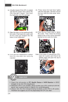
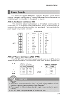
Hardware Setup Power Supply The mainboard supports ATX power supply for the power system. Before inserting the power supply connector, always make sure that all components are installed properly to ensure that no damage will be caused. ATX 24-Pin Power Connector: ATX This connector allows you to connect an ATX 24-pin power supply. To connect the ATX 24-pin power supply, make sure the plug of the power supply is inserted in the proper orientation and the pins are aligned. Then push down the power supply firmly into the connector. 13 ATX 24 Pin Definition 1 PIN SIGNAL PIN SIGNAL 1 +3.3V 13 +3.3V 2 +3.3V 14 -12V 3 GND 15 GND 4 +5V 16 PS-ON# 5 GND 17 GND 6 +5V 18 GND 7 GND 19 GND 8 PW R OK 20 NC 9 5VSB 21 +5V 10 +12V 22 +5V 12 11 +12V 12 +3.3V 23 +5V 24 GND ATX 12V Power Connector: JPW/ JPWR The JPW 12V power connector is used to provide power to the CPU. And the JPWR 12V power connector is used to provide power to the PCIEX16 graphics card. 48 15 JPW JPW Pin Definition PIN SIGNAL PIN SIGNAL 1 GND 2 GND 3 GND 4 GND 5 +12V 6 +12V 7 +12V 8 +12V 1 JPWR JPWR Pin Definition PIN SIGNAL 1 5V 2 GND 3 GND 4 12V Important 1. These three connectors connect to the ATX power supply and have to work together to ensure stable operation of the mainboard. 2. Power supply of 450 watts (and above) is highly recommended for system stability. 3. ATX 12V power connection should be greater than 18A. 2-9
-
 1
1 -
2
-
3
-
4
-
5
-
6
-
7
-
8
-
9
-
10
-
11
-
12
-
13
-
14
-
15
-
16
-
17
-
18
-
19
-
 20
20 -
 21
21 -
 22
22 -
 23
23 -
 24
24 -
 25
25 -
 26
26 -
 27
27 -
 28
28 -
 29
29 -
 30
30 -
31
-
32
-
33
-
34
-
35
-
36
-
37
-
38
-
39
-
40
-
41
-
42
-
43
-
44
-
45
-
46
-
47
-
48
-
49
-
50
-
51
-
52
-
53
-
54
-
55
-
56
-
57
-
58
-
59
-
60
-
61
-
62
-
63
-
64
-
65
-
66
-
67
-
68
-
69
-
70
-
71
-
72
-
73
-
74
-
75
-
76
-
77
-
78
-
79
-
80
-
81
-
82
-
83
-
84
-
85
-
86
-
87
-
88
-
89
-
90
-
91
-
92
-
93
-
94
-
95
-
96
-
97
-
98
-
99
-
100
-
101
-
102
-
103
-
104
-
105
-
106
-
107
-
108
-
109
-
110
-
111
-
112
-
113
-
114
-
115
-
116
-
117
-
118
-
119
-
120
-
121
-
122
-
123
-
124
-
125
-
126
-
127
-
128
-
129
-
130
-
131
-
132
-
133
-
134
-
135
-
136
-
137
-
138
-
139
-
140
-
141
-
142
-
143
-
144
-
145
-
146
-
147
-
148
-
149
-
150
-
151
-
152
-
153
-
154
-
155
-
156
-
157
 |
 |
