MSI 975X PLATINUM User Guide - Page 41
Edition, Primary, Ready, Second - windows 7
 |
UPC - 816909035759
View all MSI 975X PLATINUM manuals
Add to My Manuals
Save this manual to your list of manuals |
Page 41 highlights
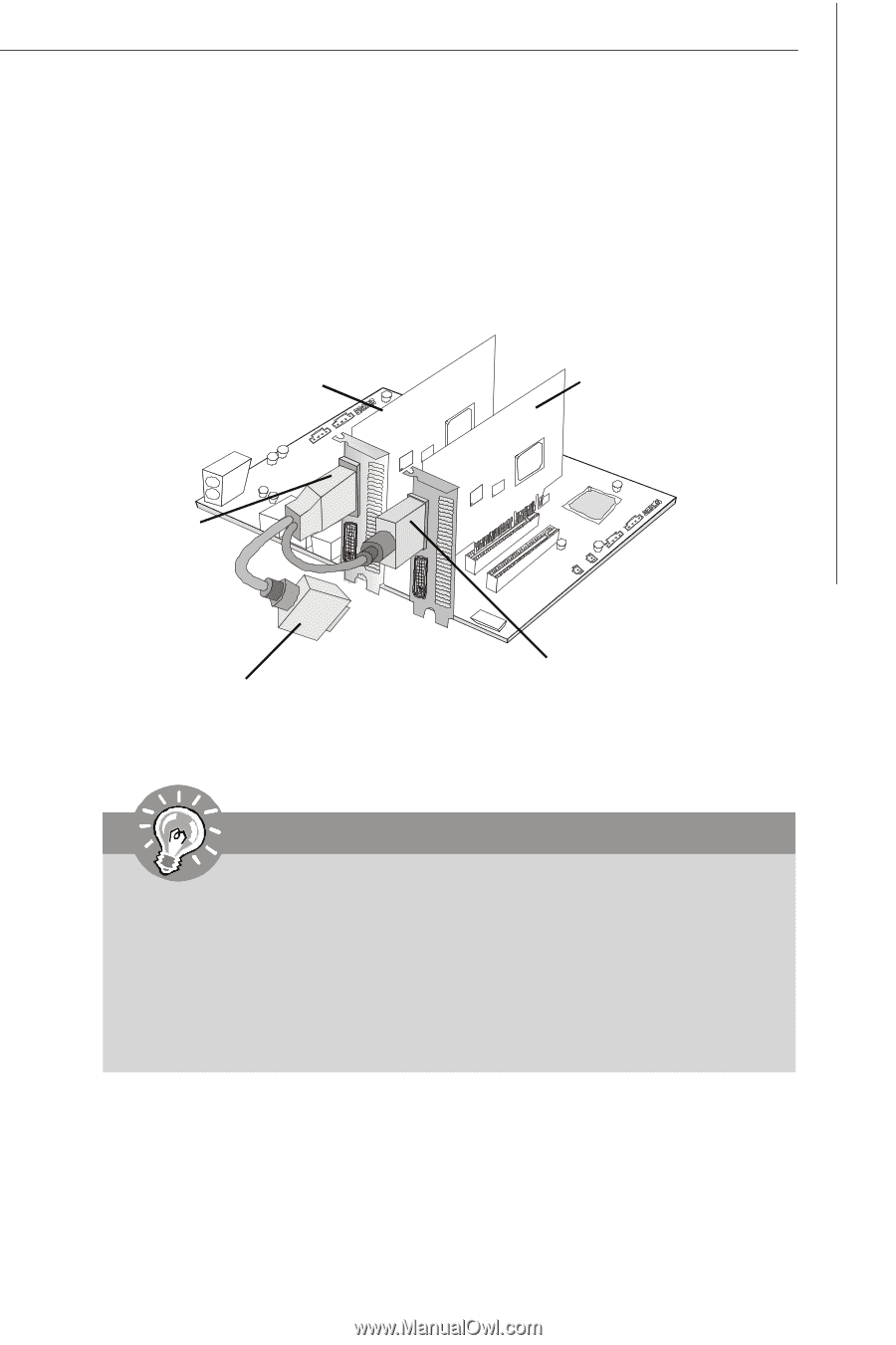
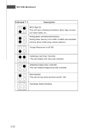
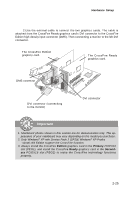
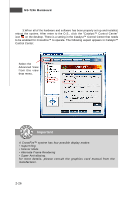
Hardware Setup 2.Use the external cable to connect the two graphics cards. The cable is attached from the CrossFire Ready graphics card's DVI connector to the CrossFire Edition high density input connector (DMS). Then connectting a monitor to the left DVI connector. The CrossFire Edition graphics card. The CrossFire Ready graphics card. DMS connector DVI connector (connectting to the monitor) DVI connector Important 1. Mainboard photos shown in this section are for demonstration only. The appearance of your mainboard may vary depending on the model you purchase. 2. Only Windows® XP with Service Pack 2 (SP2)& Windows® XP Profes -sional x64 Edition support the CrossFire function. 3. Always install the CrossFire Edition graphics card in the Primary PCIEX16 slot (PEG1), and install the CrossFire Ready graphics card in the Secondary PCIEX16 slot (PEG2) to make the CrossFire technology functions pr op er ly . 2-25
-
 1
1 -
2
-
3
-
4
-
5
-
6
-
7
-
8
-
9
-
10
-
11
-
12
-
13
-
14
-
15
-
16
-
17
-
18
-
19
-
20
-
21
-
22
-
23
-
24
-
25
-
26
-
27
-
28
-
29
-
30
-
31
-
32
-
33
-
34
-
35
-
 36
36 -
 37
37 -
 38
38 -
 39
39 -
 40
40 -
 41
41 -
 42
42 -
 43
43 -
 44
44 -
 45
45 -
 46
46 -
47
-
48
-
49
-
50
-
51
-
52
-
53
-
54
-
55
-
56
-
57
-
58
-
59
-
60
-
61
-
62
-
63
-
64
-
65
-
66
-
67
-
68
-
69
-
70
-
71
-
72
-
73
-
74
-
75
-
76
-
77
-
78
-
79
-
80
-
81
-
82
-
83
-
84
-
85
-
86
-
87
-
88
-
89
-
90
-
91
-
92
-
93
-
94
-
95
-
96
-
97
-
98
-
99
-
100
-
101
-
102
-
103
-
104
-
105
-
106
-
107
-
108
-
109
-
110
-
111
-
112
-
113
-
114
-
115
-
116
-
117
-
118
-
119
-
120
-
121
-
122
-
123
-
124
-
125
-
126
-
127
-
128
-
129
-
130
-
131
-
132
-
133
-
134
-
135
-
136
-
137
-
138
-
139
-
140
-
141
-
142
-
143
-
144
-
145
-
146
-
147
-
148
-
149
-
150
-
151
-
152
-
153
-
154
-
155
-
156
-
157
 |
 |