MSI 975X PLATINUM User Guide - Page 27
USB Connectors, Serial Port Connector: COM Port
 |
UPC - 816909035759
View all MSI 975X PLATINUM manuals
Add to My Manuals
Save this manual to your list of manuals |
Page 27 highlights
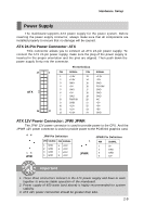
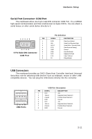
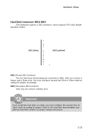
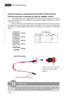
Hardware Setup Serial Port Connector: COM Port The mainboard offers one 9-pin male DIN connector COM Port. It's a 16550A high speed communication port that send/receive/ 16 bytes FIFOs. You can attach a serial mouse or other serial device directly to it. 1 2 3 4 5 PIN 1 2 3 4 6 7 8 9 5 9-Pin Male DIN Connector 6 7 COM Port 8 9 Pin Definition SIGNAL DCD SIN SOUT DTR GND DSR RTS CTS RI DESCRIPTION Data Carry Detect Serial In or Receive Data Serial Out or Transmit Data Data Terminal Ready) Ground Data Set Ready Request To Send Clear To Send Ring Indicate USB Connectors The mainboard provides an OHCI (Open Host Controller Interface) Universal Serial Bus root for attaching USB devices such as keyboard, mouse or other USBcompatible devices. You can plug the USB device directly into the connector. 1 23 4 5 67 8 USB Ports USB Port Description PIN SIGNAL 1 VCC 2 -Data 0 3 +Data0 4 GND 5 VCC 6 -Data 1 7 +Data 1 8 GND DESCRIPTION +5V Negative Data Channel 0 Positive Data Channel 0 Ground +5V Negative Data Channel 1 Positive Data Channel 1 Ground 2-11
-
 1
1 -
2
-
3
-
4
-
5
-
6
-
7
-
8
-
9
-
10
-
11
-
12
-
13
-
14
-
15
-
16
-
17
-
18
-
19
-
20
-
21
-
 22
22 -
 23
23 -
 24
24 -
 25
25 -
 26
26 -
 27
27 -
 28
28 -
 29
29 -
 30
30 -
 31
31 -
 32
32 -
33
-
34
-
35
-
36
-
37
-
38
-
39
-
40
-
41
-
42
-
43
-
44
-
45
-
46
-
47
-
48
-
49
-
50
-
51
-
52
-
53
-
54
-
55
-
56
-
57
-
58
-
59
-
60
-
61
-
62
-
63
-
64
-
65
-
66
-
67
-
68
-
69
-
70
-
71
-
72
-
73
-
74
-
75
-
76
-
77
-
78
-
79
-
80
-
81
-
82
-
83
-
84
-
85
-
86
-
87
-
88
-
89
-
90
-
91
-
92
-
93
-
94
-
95
-
96
-
97
-
98
-
99
-
100
-
101
-
102
-
103
-
104
-
105
-
106
-
107
-
108
-
109
-
110
-
111
-
112
-
113
-
114
-
115
-
116
-
117
-
118
-
119
-
120
-
121
-
122
-
123
-
124
-
125
-
126
-
127
-
128
-
129
-
130
-
131
-
132
-
133
-
134
-
135
-
136
-
137
-
138
-
139
-
140
-
141
-
142
-
143
-
144
-
145
-
146
-
147
-
148
-
149
-
150
-
151
-
152
-
153
-
154
-
155
-
156
-
157
 |
 |
