McAfee IIP-M80K-ISAA Product Guide - Page 29
Cable types for routers, switches, hubs, and PCs, Cabling for in-line, Cabling for TAP mode
 |
View all McAfee IIP-M80K-ISAA manuals
Add to My Manuals
Save this manual to your list of manuals |
Page 29 highlights
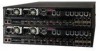
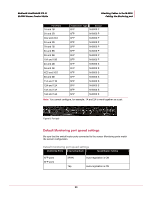
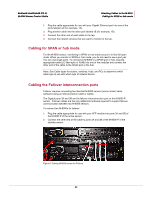
McAfee® IntruShield® IPS 4.1 M-8000 Sensor Product Guide Attaching Cables to the M-8000 Cabling for in-line Monitoring Ports Operating Mode Speed/Duplex Setting In-line Auto-negotiation is ON Cable types for routers, switches, hubs, and PCs The cabling instructions in this chapter • Use a crossover Ethernet RJ-45 cable to connect a router port to the 10/100/1000 copper SFP Monitoring ports. • Use a straight-through Ethernet RJ-45 cable to connect a switch/hub port to 10/100/1000 copper SFP Monitoring ports. • Use a crossover Ethernet RJ-45 cable to connect a router port to PC to the sensor Management port. Note: You should also use a crossover Ethernet RJ-45 cable to connect a PC to the sensor monitoring port. Cabling for in-line The Gigabit Ethernet ports fail closed, meaning they stop the flow of traffic if the sensor fails. To allow traffic to flow uninterrupted, you must use special hardware and cable the sensor for fail-open functionality. For instructions, see the section later in this chapter. To connect the M-8000's Gigabit Ethernet ports so they fail closed: 1 Plug the cable appropriate for use with your Gigabit Ethernet into one of the ports labeled xA (for example, 1A). 2 Plug another cable into the peer of the port used in Step 1. This port will be labeledxB (for example, 1B). 3 Connect the other end of each cable to the network devices that you want to monitor. (For example, if you plan to monitor traffic between a switch and a router, connect the cable connected to 1A to the switch and the one connected to 1B to the router.) Cabling for TAP mode The M-8000 sensor's Gigabit Ethernet ports must be used with a 3rd party external tap. Note: For a list of approved 3rd party vendors, see the KnowledgeBase at https://mysupport.mcafee.com External tap mode requires a port pair (for example, 1A and 1B). To connect the sensor to the devices you want to monitor in external tap mode: 21
-
 1
1 -
2
-
3
-
4
-
5
-
6
-
7
-
8
-
9
-
10
-
11
-
12
-
13
-
14
-
15
-
16
-
17
-
18
-
19
-
20
-
21
-
22
-
23
-
 24
24 -
 25
25 -
 26
26 -
 27
27 -
 28
28 -
 29
29 -
 30
30 -
 31
31 -
 32
32 -
 33
33
 |
 |
