Nikon D7000 D7000 User's Manual - Page 248
e4: Modeling Flash, The Flash Sync Mode Display, Built, in flash, Flash Compensation, Commander mode
 |
UPC - 018208254743
View all Nikon D7000 manuals
Add to My Manuals
Save this manual to your list of manuals |
Page 248 highlights
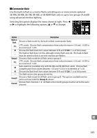
A The Flash Sync Mode Display M does not appear in the control panel flash sync mode display when - - is selected for Builtin flash > Mode. A Flash Compensation The flash compensation value selected with the Y (M) button and sub-command dial is added to the flash compensation values selected for the built-in flash, group A, and group B in the Commander mode menu. A Y icon is displayed in the control panel and viewfinder when a flash compensation value other than ±0 is selected for Built-in flash > TTL. The Y icon flashes when the built-in flash is in mode M. D Commander Mode Position the sensor windows on the remote flash units to pick up the monitor preflashes from the built-in flash (particular care is required if the camera is not mounted a tripod). Be sure that direct light or strong reflections from the remote flash units do not enter the camera lens (in TTL mode) or the photocells on the remote flash units (AA mode), as this may interfere with exposure. To prevent timing flashes emitted by the built-in flash from appearing in photographs taken at short range, choose low ISO sensitivities or small apertures (large f-numbers) or use an optional SG-3IR infrared panel for the built-in flash. An SG-3IR is required for best results with rear-curtain sync, which produces brighter timing flashes. After positioning the remote flash units, take a test shot and view the results in the camera monitor. Although there is no limit on the number of remote flash units that may be used, the practical maximum is three. With more than this number, the light emitted by the remote flash units will interfere with performance. e4: Modeling Flash G button ➜ A Custom Settings menu If On is selected when the camera is being used with the built-in flash or an optional SB-900, SB-800, SB-700, SB-600, or SB-R200 flash unit, a modeling flash will be emitted when the camera depth-of-field preview button is pressed (0 72). No modeling flash is emitted if Off is selected. U 228
-
 1
1 -
2
-
3
-
4
-
5
-
6
-
7
-
8
-
9
-
10
-
11
-
12
-
13
-
14
-
15
-
16
-
17
-
18
-
19
-
20
-
21
-
22
-
23
-
24
-
25
-
26
-
27
-
28
-
29
-
30
-
31
-
32
-
33
-
34
-
35
-
36
-
37
-
38
-
39
-
40
-
41
-
42
-
43
-
44
-
45
-
46
-
47
-
48
-
49
-
50
-
51
-
52
-
53
-
54
-
55
-
56
-
57
-
58
-
59
-
60
-
61
-
62
-
63
-
64
-
65
-
66
-
67
-
68
-
69
-
70
-
71
-
72
-
73
-
74
-
75
-
76
-
77
-
78
-
79
-
80
-
81
-
82
-
83
-
84
-
85
-
86
-
87
-
88
-
89
-
90
-
91
-
92
-
93
-
94
-
95
-
96
-
97
-
98
-
99
-
100
-
101
-
102
-
103
-
104
-
105
-
106
-
107
-
108
-
109
-
110
-
111
-
112
-
113
-
114
-
115
-
116
-
117
-
118
-
119
-
120
-
121
-
122
-
123
-
124
-
125
-
126
-
127
-
128
-
129
-
130
-
131
-
132
-
133
-
134
-
135
-
136
-
137
-
138
-
139
-
140
-
141
-
142
-
143
-
144
-
145
-
146
-
147
-
148
-
149
-
150
-
151
-
152
-
153
-
154
-
155
-
156
-
157
-
158
-
159
-
160
-
161
-
162
-
163
-
164
-
165
-
166
-
167
-
168
-
169
-
170
-
171
-
172
-
173
-
174
-
175
-
176
-
177
-
178
-
179
-
180
-
181
-
182
-
183
-
184
-
185
-
186
-
187
-
188
-
189
-
190
-
191
-
192
-
193
-
194
-
195
-
196
-
197
-
198
-
199
-
200
-
201
-
202
-
203
-
204
-
205
-
206
-
207
-
208
-
209
-
210
-
211
-
212
-
213
-
214
-
215
-
216
-
217
-
218
-
219
-
220
-
221
-
222
-
223
-
224
-
225
-
226
-
227
-
228
-
229
-
230
-
231
-
232
-
233
-
234
-
235
-
236
-
237
-
238
-
239
-
240
-
241
-
242
-
 243
243 -
 244
244 -
 245
245 -
 246
246 -
 247
247 -
 248
248 -
 249
249 -
 250
250 -
 251
251 -
 252
252 -
 253
253 -
254
-
255
-
256
-
257
-
258
-
259
-
260
-
261
-
262
-
263
-
264
-
265
-
266
-
267
-
268
-
269
-
270
-
271
-
272
-
273
-
274
-
275
-
276
-
277
-
278
-
279
-
280
-
281
-
282
-
283
-
284
-
285
-
286
-
287
-
288
-
289
-
290
-
291
-
292
-
293
-
294
-
295
-
296
-
297
-
298
-
299
-
300
-
301
-
302
-
303
-
304
-
305
-
306
-
307
-
308
-
309
-
310
-
311
-
312
-
313
-
314
-
315
-
316
-
317
-
318
-
319
-
320
-
321
-
322
-
323
-
324
-
325
-
326
-
327
-
328
-
329
-
330
-
331
-
332
-
333
-
334
-
335
-
336
-
337
-
338
-
339
-
340
-
341
-
342
-
343
-
344
-
345
-
346
-
347
-
348
 |
 |