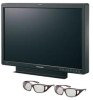
Panasonic BT-3DL2550 Operating Instructions - Page 17
How to Use the On Screen Menu
 |
View all Panasonic BT-3DL2550 manuals
Add to My Manuals
Save this manual to your list of manuals |
Page 17 highlights
How to Use the On Screen Menu The screen displays eight types of information: input signal status, picture/volume adjusting menu status, sharpness display, FUNCTION display, audio level meter display, menu display, TIME CODE display and CLOSED CAPTION display. Input signal status _ 2D mode _ 3D mode 7 8 9 35 6 3D SIMUL LINE BY LINE SDI1(L): 1080/59.94i(L) SDI2(R): 1080/59.94i(R) 1. Main window , sub-window indication • Indicates whether the main window or sub-window is displayed. • In split screen display, the screen synchronized to the reference sync changes with the input signal format and "TWO WINDOW SIZE" settings (J page 47). The screen synchronized to the reference sync is displayed in white and the screen that is not synchronized is displayed in yellow. 2. The selected input line (J page 13, 7 ) • VIDEO, SDI1, SDI2, YPBPR/RGB-VIDEO/RGB-COMP. DVI-VIDEO/DVI-COMP. • Use "STATUS DISPLAY" in the "SYSTEM CONFIG" menu to set the display status (J page 32). 3. Various indications (FILM mode) • This indicates that "GAMMA SELECT" is set to "FILM" in the "VIDEO CONFIG" menu. 4. Signal format • Use "STATUS DISPLAY" in the "SYSTEM CONFIG" menu to set the display status (J page 32). • "UNSUPPORT SIGNAL" appears if an unsupported signal is input. It may also indicate that the format selected in the "INPUT SELECT" menu does not match the input signal. • "NO SIGNAL" appears if no signal is input. Note: "UNSUPPORT SIGNAL" and "NO SIGNAL" may not be properly displayed. 5. Various indications (Lock status) • This indicates that "CONTROL" is set to "REMOTE" in the "CONTROL" menu. 10 12 11 12 6. 3D display • This indicates that "SYSTEM" is set to "3D" in the "3D" menu. 7. 3D INPUT TYPE display • This indicates the "3D INPUT TYPE" of the "3D" menu 8. SIMUL MODE display • This indicates the options for "SIMUL MODE" when "3D INPUT TYPE" is set to "SIMUL" in the "3D" menu. 9. H SHIFT display • This is displayed when the "3D INPUT TYPE" of the "3D" menu is set to "SIMUL" and the SDI2 signal is being shifted horizontally using "H SHIFT". 10. SDI1 (L) display • This indicates the format of the signal input from the SDI1 (L) terminal. When SIMUL is selected, synchronization is performed based on the left signal. 11. SDI2 (R) display • This indicates the format of the signal input from the SDI2 (R) terminal. When SIMUL is selected, synchronization is performed based on the left signal. 12. (L)(R) display • This displays left and right information when a signal that has left and right information superimposed (such as AG-3DA1) is input through SDI1. If left and right input is mistakenly reversed, it is displayed in yellow. Left and right information is not displayed if it is input through SDI2 only. 17
-
 1
1 -
2
-
3
-
4
-
5
-
6
-
7
-
8
-
9
-
10
-
11
-
 12
12 -
 13
13 -
 14
14 -
 15
15 -
 16
16 -
 17
17 -
 18
18 -
 19
19 -
 20
20 -
 21
21 -
 22
22 -
23
-
24
-
25
-
26
-
27
-
28
-
29
-
30
-
31
-
32
-
33
-
34
-
35
-
36
-
37
-
38
-
39
-
40
-
41
-
42
-
43
-
44
-
45
-
46
-
47
-
48
-
49
-
50
-
51
-
52
-
53
-
54
-
55
-
56
-
57
-
58
-
59
-
60
-
61
-
62
-
63
-
64
 |
 |
