Panasonic CF-29CRKGZKM Service Manual
Panasonic CF-29CRKGZKM - Toughbook 29 - Pentium M 1.2 GHz Manual
 |
UPC - 092281833422
View all Panasonic CF-29CRKGZKM manuals
Add to My Manuals
Save this manual to your list of manuals |
Panasonic CF-29CRKGZKM manual content summary:
- Panasonic CF-29CRKGZKM | Service Manual - Page 1
Model No. CF-29NTQGZBM ORDER NO. CPD0604068C1 Notebook Computer CF-29 This is the Service Manual for the following areas. M ...for U.S.A. and Canada © 2006 Matsushita Electric Industrial Co., Ltd. All rights reserved. Unauthorized copying and distribution is a violation of law. - Panasonic CF-29CRKGZKM | Service Manual - Page 2
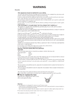
you lose the fuse cover the plug must not be used until a replacement cover is obtained. A replacement fuse cover can be purchased from your local Panasonic Dealer. IF THE FITTED MOULDED PLUG IS UNSUITABLE FOR THE SOCKET OUTLET IN YOUR HOME THEN THE FUSE SHOULD BE REMOVED AND THE PLUG CUT - Panasonic CF-29CRKGZKM | Service Manual - Page 3
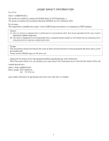
The serviceman should not remove the cover of drive unit and should not service because the drive unit is a nonserviceable part. Please check DANGER label on front panel door to look into the interior of the unit. LASER Specification Class 1 level LASER Product Wave Length: DVD 658±8 nm CD 775 - Panasonic CF-29CRKGZKM | Service Manual - Page 4
3 - Panasonic CF-29CRKGZKM | Service Manual - Page 5
4 - Panasonic CF-29CRKGZKM | Service Manual - Page 6
CONTENTS 1 Diagnosis Procedure 1-1 2 Power-On Self Test (Boot Check 2-1 3 List of Error Codes 3-1 4 Diagnostic Test 4-1 5 Self Diagnosis Test 5-1 6 Wiring Connection Diagram 6-1 7 Disassembly/Reassembly 7-1 8 Exploded View 8-1 9 Replacement Parts List 9-1 - Panasonic CF-29CRKGZKM | Service Manual - Page 7
1 Diagnosis Procedure 1.1. Basic Procedure 1-1 - Panasonic CF-29CRKGZKM | Service Manual - Page 8
to start', 'No display on screen', etc. 2. Explanation of each trouble, mainly symptom of trouble in operation. Flow Chart SSTTAARRTT Pay attention to the following points when in pursuit of the cause of a troubleshooting. 1. Peripheral apparatus connected with the set should all be removed before - Panasonic CF-29CRKGZKM | Service Manual - Page 9
beep sound or error code. Start Test begins automatically when power switch is set to ON. Normal finish .....After memory checking, a beep sound is issued once and the set is placed into automatic stop. Note: If no error offering (Note) A beep sound is also issued in case of other I/O trouble. 2-1 - Panasonic CF-29CRKGZKM | Service Manual - Page 10
problems. If your system displays one of except the messages marked below with an asterisk (*), write down the message and contact Panasonic Technical Support was detected. 0232 Extended RAM Failed at offset: nnnn Extended memory not working or not configured properly at offset nnnn. 0250 System - Panasonic CF-29CRKGZKM | Service Manual - Page 11
- Cache disabled Contact Panasonic Technical Support. 02F0: CPU ID: CPU socket number for Multi-Processor error. 02F4: EISA CMOS not writable ServerBIOS2 test error: Cannot write to EISA CMOS. 02F5: DMA Test Failed ServerBIOS2 test error: Cannot write to extended DMA (Direct Memory Access) registers - Panasonic CF-29CRKGZKM | Service Manual - Page 12
/2 mouse plug pin3). Connect pins 3-4-7-9-10-12 to VC5 (PS/2 mouse plug pin4) with 4.7KW each. CAUTION The plug described above must be used for servicing purpose only. Do not use it for other than the above purpose and ensure that it remains confidential. Using the plug enables the user to - Panasonic CF-29CRKGZKM | Service Manual - Page 13
out the Automatic test and Peripheraltest. Starting up the setup utility Turn on the power. When "Panasonic Press F2 to enter setup" appears on the screen, press F2. Press " " to test only when necessary. Problems in the unit are located and divided according to error messages that occur during - Panasonic CF-29CRKGZKM | Service Manual - Page 14
) A20 GATE TEST CACHE ON/OFF TEST 5 NPU OPERAND TEST 6 RAM (Memory related) RAM STANDARD TEST 7 CONTROL DMA PAGE REG TEST 8 (Control ICs on the main DMA REGISTER TEST 9 board, etc.) DMAC TRANSFER TEST 10 PIC HALT INSTRUCTION TEST 11 PIC REGISTER TEST 12 RTC CMOS RAM TEST 13 RTC TEST - Panasonic CF-29CRKGZKM | Service Manual - Page 15
test is stopped when an error occurs and the error message is displayed. For explanations of error messages, see Error Messages and Problem Categories (section 5.5). Quitting the test At the screen shown below, simultaneously press the ALT and X keys. Input screen 5.3. Peripheral Test Test execution - Panasonic CF-29CRKGZKM | Service Manual - Page 16
condition settings for to be changed, press "A" for Additional- custom test items. and "R" for Erase. Example: All initial VAlues are "0" so set CF-29. * * * TEST1. * * * tests other than the necessary ones to "1". Press "O" twice to return the menu screen. To save the selected list, press - Panasonic CF-29CRKGZKM | Service Manual - Page 17
5.5. Error Messages and Troubleshooting The table below explains the parts that NPU OPERAND TEST 4 RAM (Memory related) RAM STANDARD 5 CONTROL DMA PAGE REG TEST 6 (Control ICs on the DMA REGISTER TEST 7 main board, etc.) DMAC Transfer TEST 8 PIC HALT INSTRUCTION TEST 9 PIC REGISTER TEST - Panasonic CF-29CRKGZKM | Service Manual - Page 18
6 Wiring Connection Diagram SERIAL PORT CN704 IO PCB PARALLEL PORT CN703 CN700 EXTERNAL DISPLAY PORT CN702 INVERTER PCB CN1 CN2 BACK LIGHT TOUCH SCREEN CN850 LCD MDC MODEM J2 J1 MODEM PORT TS PCB CN1 CN851 PORT-REPLICATOR CN13 MIC HEADPHON USB PORT USB PORT DC-IN JK2 JK1 CN55 JK3 - Panasonic CF-29CRKGZKM | Service Manual - Page 19
or hibernation mode; abnormal operation may result. 7.1. Disassembly Instructions 7.1.1. Preparation Before disassembling, be sure to make the following off the power. • Disconnect the AC adaptor. • Remove the optional DIMM memory card and PCMCIA card if they are connected. • Remove other devices if - Panasonic CF-29CRKGZKM | Service Manual - Page 20
7.1.4. Removing the KB Cover, Hinge Cover L, Hinge Cover R and Keyboard Hinge Cover L KB Cover Hinge Cover R 7.1.5. Remove the KB Cable Cover, Keyboard and PCMCIA Protector KB Cable Cover to Connector (CN933) - Panasonic CF-29CRKGZKM | Service Manual - Page 21
7.1.6. Removing the KBD PCB, MDC Modem and LCD Cable/MIC Frame Connector CN950 (front side) Connector CN952 (reverse side) Connector J1 (reverse side) MDC Modem 7.1.7. Removing the DIMM Cover and Bottom Cover DIMM Cover KBD PCB Connector CN930 (reverse side - Panasonic CF-29CRKGZKM | Service Manual - Page 22
7.1.8. Removing the Speaker Heat Pipe Unit Bottom LCD Lamp Sheet Coil Cooling Sheet LAN Heat Plate MP Eject BOUSUI Plate MP Eject Spring MP Eject Lever MP Eject Slide Ass'y Speaker Angle Speaker 7.1.9. Removing the Wireless Module and SD PCB - Panasonic CF-29CRKGZKM | Service Manual - Page 23
7.1.10. Removing the PAD SW FFC Cover PAD SW FFC Cover Power Cable Guard 7.1.11. Removing Main PCB, EXT Antenna PCB, PCMCIA Unit and RTC Battery EXT Antenna PCB Connector CN51 (front side) Connector CN1 Connector CN6 (reverse side) Connector CN9 ( - Panasonic CF-29CRKGZKM | Service Manual - Page 24
Screws : DFHM5054XA Screws :DFHE5025XA Screws :DFHE5025XA Screws : DRQT2+G6FKL Screw : DRHM5104ZA Screw : DFHE5025ZA Screw : DRHM5117ZA 7.1.12. Remove the HDD Main FPC CN Spacer HDD Connector HDD Main FPC Battery Connector Batt HDD CN Angle - Panasonic CF-29CRKGZKM | Service Manual - Page 25
7.1.15. Removing the Palm Top Cover Sheet, Palm Top Cover, Touch Pad Adhesion Seat, Touch Pad, Touch Pad SW Knob, LED PCB and SW LED PCB 7.1.16. Removing the Handle and Power SW Handle Base L Palm Top Cover Sheet Palm Top Cover Power SW Handle Handle Base R LED - Panasonic CF-29CRKGZKM | Service Manual - Page 26
7.1.17. Removing LCD Unit LCD unit 7.1.18. Removing LCD Rear Cabinet, Hinge L and Hinge R LCD Latch LCD Rear Cabinet Hinge L Hinge R Figure 16 1. Remove the two Screws and the four Screws, - Panasonic CF-29CRKGZKM | Service Manual - Page 27
7.1.19. Removing the Inverter PCB, TS PCB and LCD Unit Inverter PCB TS PCB LCD Unit LCD Front Cabinet Figure 18 1. Disconnect two Cables from Connectors. (on Inverter PCB) 2. Remove the Inverter PCB. 3. Disconnect two Cables from Connectors. (on TS PCB) 4. Remove the TS PCB. 5. Remove the LCD - Panasonic CF-29CRKGZKM | Service Manual - Page 28
7.2. Reassembly Instructions 7.2.1. Attention when CF-29 series is repaired • Please execute writing BIOS ID when you exchange the Main Board. • You cannot reuse the Conductive Clothes and the heat dissipating - Panasonic CF-29CRKGZKM | Service Manual - Page 29
7.2.3. Setting the Inverter PCB, TS PCB and LCD Unit 1. Set the LCD Unit to the LCD Front Cabinet in order. 2. Attach the Inverter PCB to the LCD Unit and connect the two Cables to the two Connectors on the Inverter PCB. 3. Attach the TS PCB to the LCD Unit in order and connect the two Cables to the - Panasonic CF-29CRKGZKM | Service Manual - Page 30
n Arranging the Inverter PCB 1. Attach the LCD Inverter Case Spacer L to the Inverter PCB. 2. Attach the Inverter Case L/U to the Inverter Case L. Inverter Case U Align View "A" LCD Inverter Case View "A" 1~2mm Spacer L 1~2mm LCD Inverter Case Spacer L Inverter PCB Do not pressure to trance - Panasonic CF-29CRKGZKM | Service Manual - Page 31
n Arranging the LCD Back Holder 1. Attach the two LCD Cable Tapes to the LCD Back Holder. LCD Back Holder 0~1mm Bend 30 Bend 30 LCD Cable Tape 0~1mm Bend 90 n Attaching the LCD Damper Front, LCD Side Damper UN/R13 and TS Spacer L13/S13 1. Attach the LCD Damper Front to the upper part of the - Panasonic CF-29CRKGZKM | Service Manual - Page 32
n Attaching the LCD Thermal Plate, LCD Hold Plate L and LCD Hold Plate R 1. Attach the LCD Thermal Plate to the LCD Unit. 2. Fix the LCD Plate L and LCD Hold Plate R to sides of the LCD Unit using the two Screws. Screws : DXYN2+C3FNL LCD Plate R LCD Unit LCD Hold Plate L LCD Metal Damper - Panasonic CF-29CRKGZKM | Service Manual - Page 33
n Attaching the Inverter PCB and TS PCB 1. Attach the Inverter PCB to the LCD Back Holder of the LCD Unit and connect the two Cables to the two Connectors on the Inverter PCB. 2. Attach the TS PCB to the LCD Back Holder of the LCD Unit and connect the two Cables to the two Connectors on TS PCB. - Panasonic CF-29CRKGZKM | Service Manual - Page 34
n Arranging the Cables Safety Working TS PCB IC TS FFC Sheet 0~1mm View "A" View "B" Sheet 8±1mm 0~1mm Kapton Tape Draw out the rest of Cable in a direction of the arrow. View "B" Inverter PCB View "A" TS FFC Sheet 0~1mm IC Press TS PCB LCD Plate R View "B" Inverter Case Cable Pass - Panasonic CF-29CRKGZKM | Service Manual - Page 35
7.2.4. Setting the LCD Rear Cabinet, Hinge L and Hinge R 1. Fix the Hinge L and R using the two Screws. 2. Set the Latch. 3. Set the LCD Front Cabinet to the LCD Rear Cabinet. 4. Fix the LCD Front Cabinet using the two Screws. No1, No2 5. Fix the LCD Front Cabinet using the ten Screws. - Panasonic CF-29CRKGZKM | Service Manual - Page 36
7.2.6. Setting the Handle and Power SW 1. Set the Power SW. 2. Set the Handle. 3. Fix the Handle Base Land R using the two Screws. Screws : DRSB4+8FKL Handle Base L Power SW Handle Handle Base R 7.2.7. Setting the Palm Top Cover Sheet, Palm Top Cover, Touch Pad Adhesion Seat, - Panasonic CF-29CRKGZKM | Service Manual - Page 37
n Arranging the SW LED PCB 1. Attach the Power SW PCB Cushion and the two Tape CPU to the PW LED PCB. Power SW PCB Cushion 1±1mm 0~0.5mm 0.5±0.5mm 0~0.5mm PW LED PCB Component side 2. Bend the PW LED PCB as shown. Safety Working Bend 180 1 1±1mm 2±2mm Foil side Tape CPU PW LED PCB White - Panasonic CF-29CRKGZKM | Service Manual - Page 38
n Arranging the Power SW Cable Top Cabinet Safety Working Set the Cable along a connector side, not to prop. SW LED PCB View "A" Tape Power SW Cable CON Spacer View "B" 0~2mm View "A" Do not put up the Cable on the Cabinet. Tape CON Spacer 0~2mm 3~4mm Power SW Cable 0~0.5mm 0~2mm View - Panasonic CF-29CRKGZKM | Service Manual - Page 39
7.2.8. Setting the IO PCB 1. Fix the IO PCB using the six Screws. No1 to No6 Note: Tighten the Screws in the numbered order (No1 to No6). Screws : DFHE5058ZB Rear I/O FPC Cover Sheet IO PCB :No1 :No3 :No4 :No5 :No6 :No2 n Arrange the IO FPC Safety Working - Panasonic CF-29CRKGZKM | Service Manual - Page 40
n Setting the IO FPC IO FPC FCC CN Stopper IO PCB n Setting the IO PCB and attaching the Rear I/O FPC Cover Sheet IO PCB LID SW Cushion IO FPC Rib Rear I/O FPC Cover Sheet IO PCB Rib Slot Do not put up the IO FPC on the Rib. Do not put up the Rear I/O FPC Cover Sheet on the Rib. 7-22 - Panasonic CF-29CRKGZKM | Service Manual - Page 41
7.2.9. Setting the TP PCB 1. Fix the TP PCB using the two Screws. No1, No2 2. Connect the three Cables to the three Connectors on the TP PCB (CN800, CN801, CN803). Note: Tighten the Screws in the numbered order (No1, No2). Screws : DRHM0002ZA Connector CN801 :No1 :No2 Connector - Panasonic CF-29CRKGZKM | Service Manual - Page 42
7.2.10. Setting the HDD Main FPC 1. Fix the HDD Main FPC to the Batt HDD CN Angle using the two Screws and the two Screws 2. Fix the CN Spacer to the Batt HDD CN Angle using the Screw. 3. Fix the Batt HDD CN Angle using the Screw. Screw : DFHE5092ZA Screw : DFHE5025ZA Screws : - Panasonic CF-29CRKGZKM | Service Manual - Page 43
7.2.11. Setting the Main PCB, EXT Antenna PCB, PCMCIA Unit and RTC Battery 1. Connect the Cable the Connector (CN4) on the Main PCB, and Attach the RTC Battery. 2. Fix the PCMCIA to the Main PCB using the Screws. No1 to No4 3. Connect the six Cables to the six Connectors. (Main PCB: CN6, CN9, - Panasonic CF-29CRKGZKM | Service Manual - Page 44
n Attaching the SD INS Sheet, Coil Cooling Sheet and MINI PCI Spacers MINI PCI Spacers IC Coil Cooling Sheet IC SD INS Sheet n Setting the LAN Cable and Modem Cable 1. Set the LAN Cable and the Modem Cable to the DC/USB Cover Frame. 2. Set the Clampers to the LAN Cable and the Modem Cable. 3. - Panasonic CF-29CRKGZKM | Service Manual - Page 45
n Setting the Main PCB 1. Set the Main PCB to the Top Cabinet in order. Confirm that the Pin of the Top Cabinet of the hole of the Main PCB. View "C" Safety Working Pass the Power SW Cable through the upper side of Cable. Power SW Cable 2 Cable View "B" Safety Working Pull out the LAN Cable - Panasonic CF-29CRKGZKM | Service Manual - Page 46
n Arranging the Cables and attaching the Sheets, the Tape, the Space PWB Hold MP and the Insulation Sheet 1. Connect the five Cables to the five Connectors. (Main PCB: CN6, CN9, CN10, CN51, CN54) 2. Attach the three Sheets, the Tape, the Space PWB Hold MP and the Insulation Sheet. Connect the - Panasonic CF-29CRKGZKM | Service Manual - Page 47
n Setting the RTC Battery 1. Connect the Cable to the Connector CN4 on the Main PCB. 2. Attach the RTC Battery to the Main PCB. Safety Working 0~1mm 1~2mm 0~1mm Connect the Connector CN4. Main PCB Gasket 1~2mm 1~2mm RTC Battery 7-29 - Panasonic CF-29CRKGZKM | Service Manual - Page 48
7.2.12. Setting the PAD SW FFC Cover 1. Set the Power Cable Guard. 2. Fix the PAD SW FFC Cover using the three Screws. No1 to No3 Note: Tighten the Screws in the numbered order (No1 to No3). Screws : DFHE5054XA PAD SW FFC Cover :No1 :No2 :No3 Power Cable Guard n Arranging the - Panasonic CF-29CRKGZKM | Service Manual - Page 49
the Connector on the Main PCB. 8. Attach the two Heat Dissipation Rubbers to the Main PCB. MINI PCI Protector Sheet SD PCB :No3 :No2 Memory Heat Plate :No1 Note: Tighten the Screws in the numbered order (No1 to No3). Screws : DFHE5025XA CD Edge Sheet MINI PCI Spacer U2 MINI PCI - Panasonic CF-29CRKGZKM | Service Manual - Page 50
n Attaching the Memory Heat Plate Memory Heat Plate IC 0~1mm 0~1mm 7.2.14. Setting the Speaker 1. Set the MP Eject Slide Ass'y to the Bottom Cover. 2. Fix the MP Eject BOUSUI Plate - Panasonic CF-29CRKGZKM | Service Manual - Page 51
7.2.15. Setting the DIMM Cover and Bottom Cover 1. Set the Bottom Cover. 2. Connect the Cable to the Connector (CN12) on the Main PCB. 3. Fix the Bottom Cover using the eight Screws. No1 to No8 4. Fix the Bottom Cover using the eight Screws. No9 to DIMM Cover :No20 :No17 :No18 - Panasonic CF-29CRKGZKM | Service Manual - Page 52
7.2.16. Setting the KBD PCB, MDC Modem and LCD Cable/MIC Frame 1. Connect the three Cables to the three Connectors (CN930, CN950, CN952) on the KBD PCB. 2. Fix the KBD PCB using the two Screws. No1, No2 3. Connect the Cable to the Connector (J2) on the MDC Modem. 4. Attach the Sheet to the MDC - Panasonic CF-29CRKGZKM | Service Manual - Page 53
n Arranging the Cables and setting the LCD Cable/MIC Frame 1. Pass the LCD Cable and Antenna Cables through the LCD Cable/MIC Frame. 2. Attach the LCD Conductive Sheet and the Gasket to the LCD Cable/MIC Frame. 3. Set the LCD Cable/MIC Frame to the Top Cabinet. View "A" LCD Conductive Sheet Top - Panasonic CF-29CRKGZKM | Service Manual - Page 54
7.2.17. Setting the KB Cable Cover, Keyboard and PCMCIA Protector 1. Fix the PCMCIA Protector using the five Screws. No1 to No6 2. Connect the two Cables of the Keyboard to the two Connectors (CN932, CN933) on the KBD PCB. 3. Set the Keyboard. :No8 :No10 :No11 :No7 : - Panasonic CF-29CRKGZKM | Service Manual - Page 55
7.2.18. Setting the KB Cover, Hinge Cover L, Hinge Cover R and Keyboard 1. Insert the front hooks of the Keyboard to the Top Cabinet in order, and set the Keyboard. 2. Fix the Hinge Cover L and R using the four Screws. No1 to No4 3. Fix the Hinge Cover L and R using the four Screws. No5 to - Panasonic CF-29CRKGZKM | Service Manual - Page 56
7.2.19. Setting the HDD 1. Set the HDD FPC to HDD. 2. Attach the Heater to HDD. 3. Attach the Heater Sheet to the Heater. 4. Attach the two Sheets to HDD. 5. Attach the six HDD Forming MFYPC and the two HDD Terminal Plate Upper to the HDD Damper Ass'y 6. Attach the six HDD Forming MFYPC and the two - Panasonic CF-29CRKGZKM | Service Manual - Page 57
7.2.20. Setting the Battery Pack, the HDD Pack and the FDD Pack 1. Set the FDD Pack. 2. Set the HDD Pack. 3. Set the Battery Pack. Battery Cover MP Cover FDD Pack Battery Pack HDD Cover HDD Pack 7-39 - Panasonic CF-29CRKGZKM | Service Manual - Page 58
K1-8 K1-15 K1-12 K1-9 K1-12 K1-13 A K1-2 K1-14 K461 K1 K1-11 A K1-2 K1-6 K1-13 K1-3 K1-8 K1-10 CF-29NTQGZBM - Panasonic CF-29CRKGZKM | Service Manual - Page 59
-1 K2-10-2 K2-22 B K2-22 B B K2-10-3 B K2-6-3 K2-5 K2-4 K2-14 K31 K866 K41 A K410 K32 K34 E48 K410 E49 A K35 K40 A K410 CF-29NTQGZBM - Panasonic CF-29CRKGZKM | Service Manual - Page 60
A K405 A E44 E42 M 0.2 +_ 0.02 N.m K868 K869 K860 W Y (2.0 +_ 0.2 kgf.cm) E789 E41 N 0.45 +_ 0.03 N.m (4.5 +_ 0.3 kgf.cm) P 0.8 +_ 0.1 N.m (8.0 _+ 1.0 kgf.cm) A K405 E790 K873 K864 K405 A K81 K52 K465 CF-29NTQGZBM - Panasonic CF-29CRKGZKM | Service Manual - Page 61
K884 B K400 K57 B K400 K880 K402 K K48 Screw tightening torque A 0.19 _+ 0.02 N.m (2.0 _+ 0.2 kgf.cm) B 0.45 _+ 0.05 N.m (4.5 _+ 0.5 kgf.cm) E 0.49 _+ 0.05 N.m (5.0 _+ 0.5 kgf.cm) K 0.8 _+ 0.1N.m (8.0 _+ 1.0 kgf.cm) CF-29NTQGZBM - Panasonic CF-29CRKGZKM | Service Manual - Page 62
Screw tightening torque A 0.19 +_ 0.02 N.m (2.0 +_ 0.2 kgf.cm) B 0.45 +_ 0.50 N.m (4.5 +_ 0.5 kgf.cm) F 0.441 +_ 0.049 N.m (4.5 +_ 0.5 kgf.cm) G 1.47 _+ 0.20 N.m (15 +_ 2.0 kgf.cm) H 1.30 _+ 0.17N.m (13.0 +_ 2.0 kgf.cm) CF-29NTQGZBM - Panasonic CF-29CRKGZKM | Service Manual - Page 63
-10 K878 Screw tightening torque A 0.19 +_ 0.02 N.m (2.0 +_ 0.2 kgf.cm) B 0.45 +_ 0.05 N.m (4.5 _+ 0.5 kgf.cm) C 0.216 +_ 0.0196 N.m (2.2 +_ 0.2 kgf.cm) D 0.314 +_ 0.0196 N.m (3.2 +_ 0.2 kgf.cm) E 0.49 +_ 0.05 N.m (5.0 +_ 0.5 kgf.cm) CF-29NTQGZBM - Panasonic CF-29CRKGZKM | Service Manual - Page 64
A 0.19 +_ 0.02 N.m (2.0 +_ 0.2 kgf.cm) B 0.45 +_ 0.05 N.m (4.5 +_ 0.5 kgf.cm) C 0.216 +_ 0.0196 N.m (2.2 +_ 0.2 kgf.cm) D 0.314 +_ 0.0196 N.m (3.2 +_ 0.2 kgf.cm) G 1.47 +_ 0.20 N.m (15 +_ 2.0 kgf.cm) O 0.49 +_ 0.05 N.m (5.0 +_ 0.5 kgf.cm) CF-29NTQGZBM - Panasonic CF-29CRKGZKM | Service Manual - Page 65
When replacing any of these components, use only manufacturer's specified parts. CF-29NTQGZBM REF.NO. and AREA Main Block Unit E1 E2 E3 E4 E5 CABLE PCMCIA EJECTOR PCB, SD-CN FFC, PAD AC ADAPTER AC CABLE MANUAL BATTERY PACK MODEM CABLE CLOTH, TOUCH PANEL PEN Q'TY RTL 1 RTL 1 RTL 1 RTL 1 - Panasonic CF-29CRKGZKM | Service Manual - Page 66
P1 DFPK1154LA PACKING CASE 1 P2 DFPE0611ZA MANUAL HOLDER 1 P3 DFPN0754XA CUSHION 1 Mechanical Parts K1 DFWV99A0105 HDD MOUNTING KIT 1 K1-1 DL3UP1268ARA FPC, HDD 1 K1-2 DFHE5025XA SCREW 4 K1-3 DFHG1696ZA LCD DUMPER 2 K1-6 DFHR8489ZA HDD - Panasonic CF-29CRKGZKM | Service Manual - Page 67
K2-10-2 DFGE0084ZA-0 HDD COVER SHEET 1 K2-10-3 DRQT26+D3KLT SCREW 2 K2-10-4 DFHR3697ZAT HDD COVER CUSHION 2 K2-11 DFKE8177ZA-0 PC LATCH ASS'Y 2 1 K2-11-1 DFBD0185ZA-0 PC LATCH LEVER 2 1 K2-11-2 DFMD1161ZA PC LATCH ANGLE 1 K2-11-3 DFUQ0089YA SPRING (MP/PC LATCH) 1 K2-11-4 - Panasonic CF-29CRKGZKM | Service Manual - Page 68
K3-25 DFHR3B66ZA LAN HEAT PLATE SPACER 1 K3-26 DFHR3B67ZA HEAT PIPE SPACER 2 K4 DFMC0685ZA CONDUCTIVE SHEET, LCD 1 K5 DFMD7929XA TOP RIB ANGLE FRONT 1 K6 DFMD9090XA BATT HDD CN ANGLE 1 K7 DFMX0635ZB SHEET 7 K8 DFMX1006ZA CABLE SHEET 2 K11 DFGT1055ZA BOTTOM COVER SHEET A - Panasonic CF-29CRKGZKM | Service Manual - Page 69
K80 K81 K83 K86 K87 K90 K92 K93 K99 K200 K200-1 K200-1-2 K200-1-3 K200-1-5 K200-6 K200-6-1 K200-6-1-1 K200-6-2 K200-11 K200-12 K200-13 K200-14 K200-19 K201 K201-1 K201-1-2 K201-1-3 K201-1-4 K201-1-5 K201-1-6 K201-9 K202 K202-1 K203 K204 K205 K206 K211 K215 K222 K223 K225 K228 K230 K235 K236 K237 - Panasonic CF-29CRKGZKM | Service Manual - Page 70
INS SHEET 1 K861 DRHM5104ZA SCREW 3 K862 DFHG1812ZA SPACE PWB HOLD MP 1 K863 DFMX1198ZA INS SHEET, HEAT PIPE 1 K864 DFMY3151ZA MEMORY HEAT PLATE 1 K865 DFGK0133ZA SD LED SHEET 1 K866 DFHR6184ZA DC USB COVER HOOK 1 K868 DFHR7518ZA INSULATION SHEET 1 K869 DFHE0965ZA FPC - Panasonic CF-29CRKGZKM | Service Manual - Page 71
K302 DFGX0178PA-0 CABINET, FDD 1 K303 DFGX0179VA-0 BACK PANEL, FDD 1 K304 DRHM5076YA SCREW 4 K305 DFHR4050ZA TUBE, LED 1 K306 DFHR5440YA GUIDE, FDD CONNECTOR 1 K308 DFHR8295ZC LS DAMPER, UNDER-1 1 K309 DFHR8296ZB LS DAMPER, UNDER-2 2 K310 DFHR8297YA DAMPER, FDD 2 K311 - Panasonic CF-29CRKGZKM | Service Manual - Page 72
: Important Safety Notice Components identified by mark have special characteristics important for safety. When replacing any of these components use only manufacturer's specified parts. CF-29NTQGZBM REF. NO and AREA Main PCB BT 1 C2 C3 C4 C6 C7 C8 C 11 C 12 C 13 C 15 C 16 C 17 C 19 C 20 C 21 C 23 - Panasonic CF-29CRKGZKM | Service Manual - Page 73
C 70 C 77 C 86 C 87 C 97 C 99 C 100 C 103 C 104 C 108 C 112 C 117 C 123 C 124 C 127 C 270 C 271 C 272 C 273 C 299 C 317 C 321 C 371 C 372 C 373 C 374 C 447 C 448 C 472 C 483 C 484 C 502 C 504 C 505 C 549 C5 EEFCD0D151ER CAPACITOR, 2V, 150µF 5 C 205 C 211 C - Panasonic CF-29CRKGZKM | Service Manual - Page 74
C 60 C 61 C 65 C 67 C 68 C 69 C 74 C 75 C 76 C 78 C 79 C 83 C 88 C 89 C 98 C 101 C 107 C 110 C 114 C 130 C 131 C 134 C 135 C 136 C 137 C 140 C 141 C 142 C 143 C 146 C 147 C 149 C 150 C 153 C 154 C 167 C 169 C 171 C 173 C 188 C 189 C 190 C 193 C 195 C 196 C 199 C 200 C 203 C 204 C 206 - Panasonic CF-29CRKGZKM | Service Manual - Page 75
C 207 C 208 C 210 C 213 C 214 C 215 C 216 C 221 C 222 C 223 C 224 C 225 C 226 C 227 C 228 C 229 C 230 C 232 C 234 C 235 C 239 C 240 C 244 C 248 C 249 C 250 C 251 C 253 C 254 C 255 C 257 C 260 C 261 C 262 C 269 C 275 C 278 C 279 C 281 C 291 C 292 C 293 C 294 C 296 C 298 C 300 C 302 C 304 C 305 C 312 - Panasonic CF-29CRKGZKM | Service Manual - Page 76
C 313 C 314 C 315 C 316 C 319 C 320 C 322 C 324 C 325 C 326 C 327 C 333 C 334 C 335 C 340 C 341 C 344 C 345 C 346 C 347 C 348 C 349 C 355 C 356 C 357 C 361 C 362 C 363 C 366 C 369 C 387 C 402 C 406 C 410 C 415 C 416 C 418 C 423 C 425 C 427 C 428 C 429 C 430 C 431 C 432 C 433 C 434 C 435 C 436 C 437 - Panasonic CF-29CRKGZKM | Service Manual - Page 77
C 438 C 439 C 440 C 441 C 442 C 443 C 444 C 445 C 446 C 452 C 453 C 454 C 455 C 457 C 466 C 468 C 470 C 476 C 477 C 485 C 490 C 495 C 500 C 576 C 589 C 593 C 598 C 627 C 628 C 629 C 630 C 631 C 632 C 633 C 50 F1G1E103A062 CAPACITOR, 25V, 0.01µF 47 C 113 C 115 - Panasonic CF-29CRKGZKM | Service Manual - Page 78
C 231 C 252 C 263 C 265 C 268 C 276 C 277 C 280 C 286 C 308 C 311 C 337 C 339 C 400 C 401 C 405 C 419 C 420 C 424 C 426 C 478 C 481 C 491 C 542 C 577 C 578 C 579 C 580 C 584 C 585 C 591 C 55 F1G1H222A450 CAPACITOR, 50V, 2200pF 2 C 389 C 56 F1G1A104A014 CAPACITOR - Panasonic CF-29CRKGZKM | Service Manual - Page 79
C 414 C 462 C 71 F1G1H102A496 CAPACITOR, 50V, 1000pF 30 C 295 C 297 C 301 C 303 C 359 C 360 C 382 C 384 C 459 C 460 C 464 C 465 C 467 C 469 C 471 C 473 C 474 C 475 C 480 C 517 C 519 C 537 C 545 C 563 C 570 C 594 C 596 C 597 C 616 C 72 EEFCX0D331R CAPACITOR, 2V, - Panasonic CF-29CRKGZKM | Service Manual - Page 80
C 350 C 352 C 353 C 354 C 367 C 368 C 377 C 378 C 380 C 385 C 386 C 391 C 392 C 102 EEFCD0D101ER CAPACITOR, 2V, 100µF 3 C 531 C 550 C 105 EEFCX0D221R CAPACITOR, 2V, 220µF 1 C 119 F1G1H270A451 CAPACITOR, 50V, 27pF 2 C 120 C 129 F1H1A1050015 CAPACITOR, 10V, 1µF 27 C 132 - Panasonic CF-29CRKGZKM | Service Manual - Page 81
C 170 C 172 C 175 F1G1H101A451 CAPACITOR, 50V, 100pF 10 C 306 C 307 C 309 C 310 C 375 C 376 C 456 C 547 C 561 C 181 F1G1H6R0A452 CAPACITOR, 50V, 6pF 2 C 258 C 187 F1G1H5R0A452 CAPACITOR, 50V, 5pF 3 C 408 C 411 C 245 EEFUD0J151ER CAPACITOR, 6.3V, 150µF 2 C 246 C 259 - Panasonic CF-29CRKGZKM | Service Manual - Page 82
C 569 C 599 C 601 C 602 C 604 C 606 C 608 C 609 C 409 F1G1C473A004 CAPACITOR, 16V, 0.047µF 2 C 590 C 449 F1L3D102A003 CAPACITOR, 2000V, 1000pF 1 C 479 F1G1H471A450 CAPACITOR, 50V, 470pF 2 C 566 C 489 F1H1H223A748 CAPACITOR, 50V, 0.022µF 1 C 494 F1J1E334A081 CAPACITOR, 25V - Panasonic CF-29CRKGZKM | Service Manual - Page 83
C 636 C 637 F1L0J107A016 CAPACITOR, 6.3V, 100µF 1 CF 1 D4CC1103A038 THERMISTOR 2 CF 2 CN 1 K1KB80A00101 CONNECTOR 1 CN 3 K1MML0B00004 CONNECTOR 1 CN 4 K1KA02AA0229 CONNECTOR 2 CN 12 CN 5 K1KBA0B00028 CONNECTOR 1 CN 6 K1KA20AA0261 CONNECTOR 1 CN 8 K1MMF4A00002 - Panasonic CF-29CRKGZKM | Service Manual - Page 84
D 62 D 27 B0JCCE000008 DIODE 1 D 29 B0JCPD000023 DIODE 3 D 52 D 53 D 31 B0JCMD000010 DIODE 5 D 34 D 36 D 37 D 39 D 32 B0ADCJ000025 DIODE 3 D 35 D 38 D 41 MAZ80510ML DIODE 5 D 43 D 44 D 46 D 47 D 45 MAZ80620ML DIODE 1 D 48 B2ABAM000002 DIODE 1 D 49 MA3S132E0L - Panasonic CF-29CRKGZKM | Service Manual - Page 85
27 C0JBAS000215 IC, GATE LOGIC 1 IC 28 C3EBFC000056 IC, EEPROM 1 IC 29 C1CB00002268 IC, SECURITY CHIP 1 IC 30 C3FBLC000040 IC, FLASH MEMORY 1 IC 31 C2CBJA000003 IC, MICON 1 IC 32 C0JBAN000235 IC, LOGIC 1 IC 33 C0JBAZ002372 IC, LOGIC 1 IC 34 C0JBAZ002346 IC, LOGIC 2 IC - Panasonic CF-29CRKGZKM | Service Manual - Page 86
IC 111 IC 106 C0JBAC000338 IC, GATE LOGIC 2 IC 201 IC 602 C0JBAD000182 IC, LOGIC 1 JK 1 K2HC103B0197 JK 1 JK 2 K2HC103B0198 JK 1 JK 3 K2EZ2B000046 JK 1 L1 G1C100Z00013 INDUCTOR 2 L2 L3 G1C1R0Z00002 INDUCTOR 5 L4 L5 L7 L8 L6 G1C91NM00001 INDUCTOR 1 L9 - Panasonic CF-29CRKGZKM | Service Manual - Page 87
Q 11 Q 14 Q 18 Q 20 Q 39 Q 105 Q 106 Q 108 Q 114 Q 121 Q 131 Q 132 Q 133 Q 134 Q 141 Q3 DETA144EETL TRANSISTOR 7 Q 58 Q 100 Q 103 Q 122 Q 135 Q 136 Q4 B1DDED000004 TRANSISTOR 6 Q 12 Q 129 Q 130 Q 137 Q 138 Q5 B1MBEDA00017 TRANSISTOR 7 Q 71 Q 76 Q 86 Q 93 Q - Panasonic CF-29CRKGZKM | Service Manual - Page 88
Q 124 Q 125 Q 126 Q 127 Q 128 Q 139 Q 13 B1DHDC000028 TRANSISTOR 11 Q 17 Q 19 Q 22 Q 25 Q 41 Q 42 Q 47 Q 48 Q 50 Q 140 Q 15 B1CFGD000004 TRANSISTOR 7 Q 16 Q 56 Q 57 Q 72 Q 77 Q 78 Q 24 XP0421300L TRANSISTOR 10 Q 26 Q 44 Q 45 Q 49 Q 55 Q 89 Q 90 Q 98 Q 117 Q - Panasonic CF-29CRKGZKM | Service Manual - Page 89
Q 88 Q 104 XP0421400L TRANSISTOR 1 Q 110 B1DHFD000015 TRANSISTOR 2 Q 112 Q 111 B1CFGD000016 TRANSISTOR 4 Q 116 Q 118 Q 119 Q 113 B1MBEDA00008 TRANSISTOR 1 Q 115 B1DHDD000031 TRANSISTOR 2 Q 120 R1 ERJ2GEJ681X RESISTOR, 1/16W, 680Ω 2 R 188 R2 ERJ2RKF27R4X RESISTOR, 1/ - Panasonic CF-29CRKGZKM | Service Manual - Page 90
R 24 ERJ2RHD102X RESISTOR, 1/16W, 1KΩ 3 R 220 R 542 R 25 ERJ2RKF2001X RESISTOR, 1/16W, 2KΩ 1 R 26 ERJ2GEJ562X RESISTOR, 1/16W, 5.6KΩ 6 R 208 R 609 R 610 R 611 R 619 R 28 ERJ2GEJ750X RESISTOR, 1/16W, 75Ω 1 R 33 ERJ2RKF2210X RESISTOR, 1/16W, 221Ω 2 R 39 R 34 ERJ2RKF1000X - Panasonic CF-29CRKGZKM | Service Manual - Page 91
R 498 R 499 R 501 R 506 R 513 R 525 R 594 R 653 R 655 R 713 R 714 R 715 R 716 R 717 R 718 R 726 R 46 ERJ2RKF80R6X RESISTOR, 1/16W, 80.6Ω 2 R 47 R 48 ERJ2GEJ103X RESISTOR, 1/16W, 10KΩ 76 R 52 R 62 R 114 R 115 R 124 R 130 R 131 R 152 R 157 R 159 R 162 R 177 R 182 - Panasonic CF-29CRKGZKM | Service Manual - Page 92
R 332 R 337 R 343 R 345 R 356 R 358 R 359 R 376 R 377 R 379 R 383 R 384 R 385 R 408 R 410 R 423 R 431 R 453 R 454 R 458 R 459 R 461 R 462 R 471 R 473 R 474 R 476 R 477 R 479 R 484 R 487 R 507 R 516 R 521 R 526 R 540 R 545 R 546 R 567 R 573 R 612 R 613 R 634 - Panasonic CF-29CRKGZKM | Service Manual - Page 93
R 266 R 371 R 373 R 51 ERJ2GEJ101X RESISTOR, 1/16W, 100Ω 19 R 158 R 160 R 176 R 184 R 235 R 236 R 281 R 402 R 405 R 428 R 460 R 478 R 596 R 598 R 599 R 600 R 601 R 602 R 53 ERJ2RKF1500X RESISTOR, 1/16W, 150Ω 6 R 54 R 55 R 258 R 259 R 260 R 57 ERJ2RKF1501X RESISTOR - Panasonic CF-29CRKGZKM | Service Manual - Page 94
R 110 R 112 R 113 R 151 R 171 R 198 R 199 R 200 R 201 R 202 R 203 R 204 R 205 R 206 R 338 R 339 R 400 R 593 R 86 ERJ2GEJ102X RESISTOR, 1/16W, 1KΩ 11 R 186 R 196 R 215 R 242 R 321 R 322 R 370 R 372 R 409 R 475 R 91 D1H83304A024 RESISTOR ARRAY 2 R 100 R 97 - Panasonic CF-29CRKGZKM | Service Manual - Page 95
R 149 ERJ2GEJ104X RESISTOR, 1/16W, 100KΩ 32 R 154 R 210 R 211 R 248 R 249 R 263 R 268 R 276 R 279 R 280 R 283 R 288 R 305 R 335 R 369 R 378 R 381 R 382 R 404 R 413 R 414 R 420 R 465 R 480 R 500 R 502 R 517 R 552 R 614 R 615 R 660 R 164 ERJ2RKF22R6X RESISTOR, 1/ - Panasonic CF-29CRKGZKM | Service Manual - Page 96
R 360 R 380 R 398 R 422 R 427 R 432 R 629 R 637 R 638 R 169 ERJ2GEJ203X RESISTOR, 1/16W, 20KΩ 1 R 170 ERJ2GEJ106X RESISTOR, 1/16W, 10MΩ 2 R 227 R 172 ERJ2GEJ105X RESISTOR, 1/16W, 1MΩ 12 R 254 R 255 R 429 R 581 R 582 R 583 R 584 R 585 R 586 R 587 R 588 R 185 - Panasonic CF-29CRKGZKM | Service Manual - Page 97
R 230 ERJ2RHD303X RESISTOR, 1/16W, 30KΩ 3 R 547 R 575 R 233 ERJ2RHD104X RESISTOR, 1/16W, 100KΩ 5 R 239 R 569 R 640 R 641 R 234 ERJ2RKD154X RESISTOR, 1/16W, 150KΩ 2 R 238 R 237 D1ZZ00000046 RESISTOR, 1W, 5mΩ 1 R 245 D1HGR008A001 RESISTOR ARRAY 3 R 246 R 247 R 253 - Panasonic CF-29CRKGZKM | Service Manual - Page 98
R 665 R 666 R 667 R 668 R 669 R 670 R 671 R 672 R 673 R 674 R 675 R 676 R 677 R 678 R 679 R 680 R 681 R 682 R 683 R 684 R 685 R 686 R 687 R 688 R 350 ERJ2GEJ363X RESISTOR, 1/16W, 36KΩ 3 R 351 R 352 R 353 ERJ2GEJ333X RESISTOR, 1/16W, 33KΩ 1 R 362 ERJ2GEJ223X - Panasonic CF-29CRKGZKM | Service Manual - Page 99
R 434 R 435 R 436 R 437 R 438 R 439 R 440 R 445 D1H87504A024 RESISTOR ARRAY 1 R 450 ERJ2RKF5602X RESISTOR, 1/16W, 56KΩ 1 R 481 ERJ2RKF1600X RESISTOR, 1/16W, 160Ω 1 R 482 ERJ2RKF2150X RESISTOR, 1/16W, 215Ω 1 R 486 ERJ2RKF7501X RESISTOR, 1/16W, 7.5KΩ 1 R 489 ERJ2RKF4531X - Panasonic CF-29CRKGZKM | Service Manual - Page 100
R 604 ERJ6GEYJ222V RESISTOR, 1/10W, 2.2KΩ 2 R 605 R 607 ERJ3GEYJ562V RESISTOR, 1/16W, 5.6KΩ 1 R 608 D1BDR4700001 RESISTOR, 1/8W, 0.47Ω 1 R 616 ERJ2RKD114X RESISTOR, 1/16W, 110KΩ 1 R 618 ERJ2RHD3652X RESISTOR, 1/16W, 36.5KΩ 1 R 620 ERJ2GEJ154X RESISTOR, 1/16W, 150KΩ 1 R 622 - Panasonic CF-29CRKGZKM | Service Manual - Page 101
C 706 C 708 C 710 C 707 F1G1H221A450 CAPACITOR, 50V, 220pF 23 C 709 C 711 C 712 C 713 C 714 C 715 C 716 C 717 C 718 C 719 C 720 C 721 C 722 C 723 C 724 C 725 C 726 C 727 C 730 C 732 C 733 C 734 C 728 F1G1H330A451 CAPACITOR, 50V, 33pF 3 C 729 C 731 C 735 - Panasonic CF-29CRKGZKM | Service Manual - Page 102
PS 700 K5J1AB000001 POLY SW 1 R 704 ERJ2GEJ472X RESISTOR, 1/16W, 4.7KΩ 9 R 705 R 706 R 707 R 708 R 709 R 710 R 711 R 712 R 713 ERJ2GEJ102X RESISTOR, 1/16W, 1KΩ 8 R 714 R 715 R 716 R 717 R 718 R 719 R 720 R 751 ERJ3GEYJ102V RESISTOR, 1/16W, 1KΩ 4 R 752 R 753 R 754 - Panasonic CF-29CRKGZKM | Service Manual - Page 103
C 855 F1G1C104A042 CAPACITOR, 16V, 0.1µF 2 C 859 C 856 F1G1H560A542 CAPACITOR, 50V, 56pF 2 C 857 CN 850 K1MN04BA0071 CONNECTOR 1 CN 851 K1KA06BA0014 CONNECTOR 1 D 850 DED1SS355T17 DIODE 1 IC 850 C1DB00001351 IC 1 Q 850 B1MBADA00003 TRANSISTOR 2 Q 852 Q 851 UNR9113J0L - Panasonic CF-29CRKGZKM | Service Manual - Page 104
CN 950 K1KA06A00454 CONNECTOR 1 LD 8 B3ABB0000210 LED 1 LD 72 B3AGB0000040 LED 1 LD 73 B3ADB0000065 LED 1 SW 950 EVQPLDA15 SW 1 EXT ANT PCB CN 1 K1QZA1AE0001 CONNECTOR 2 CN 2 CN 3 K1QZB1AA0020 CONNECTOR 1 FDD PCB C 780 F1H1H104A731 CAPACITOR, 1 CN 760 K1KAA0AA0243
-
 1
1 -
 2
2 -
 3
3 -
 4
4 -
 5
5 -
 6
6 -
 7
7 -
8
-
9
-
10
-
11
-
12
-
13
-
14
-
15
-
16
-
17
-
18
-
19
-
20
-
21
-
22
-
23
-
24
-
25
-
26
-
27
-
28
-
29
-
30
-
31
-
32
-
33
-
34
-
35
-
36
-
37
-
38
-
39
-
40
-
41
-
42
-
43
-
44
-
45
-
46
-
47
-
48
-
49
-
50
-
51
-
52
-
53
-
54
-
55
-
56
-
57
-
58
-
59
-
60
-
61
-
62
-
63
-
64
-
65
-
66
-
67
-
68
-
69
-
70
-
71
-
72
-
73
-
74
-
75
-
76
-
77
-
78
-
79
-
80
-
81
-
82
-
83
-
84
-
85
-
86
-
87
-
88
-
89
-
90
-
91
-
92
-
93
-
94
-
95
-
96
-
97
-
98
-
99
-
100
-
101
-
102
-
103
-
104
 |
 |
ORDER NO. CPD0604068C1
Notebook Computer
CF-29
Model No.
CF-29NTQGZBM
This is the Service Manual for
the following areas.
M …for U.S.A. and Canada
© 2006 Matsushita Electric Industrial Co., Ltd. All rights reserved.
Unauthorized copying and distribution is a violation of law.