Panasonic CF-29CRKGZKM Service Manual - Page 27
Remove the Antenna PCB Cover L and R and Antenna, Disconnect two Cables from Connectors. on TS PCB
 |
UPC - 092281833422
View all Panasonic CF-29CRKGZKM manuals
Add to My Manuals
Save this manual to your list of manuals |
Page 27 highlights
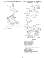
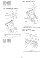
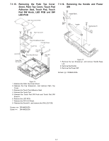
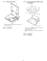
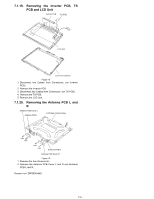
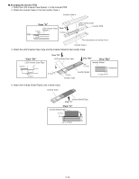
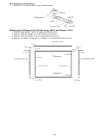
7.1.19. Removing the Inverter PCB, TS PCB and LCD Unit Inverter PCB TS PCB LCD Unit LCD Front Cabinet Figure 18 1. Disconnect two Cables from Connectors. (on Inverter PCB) 2. Remove the Inverter PCB. 3. Disconnect two Cables from Connectors. (on TS PCB) 4. Remove the TS PCB. 5. Remove the LCD Unit. 7.1.20. Removing the Antenna PCB L and R Antenna PCB Cover L Antenna PCB L LCD Rear Cabinet Ass'y Antenna PCB R Antenna PCB Cover R Figure 19 1. Remove the four Screws. 2. Remove the Antenna PCB Cover L and R and Antenna PCB L and R. Screws : DRSB26+8KL 7-9
-
 1
1 -
2
-
3
-
4
-
5
-
6
-
7
-
8
-
9
-
10
-
11
-
12
-
13
-
14
-
15
-
16
-
17
-
18
-
19
-
20
-
21
-
 22
22 -
 23
23 -
 24
24 -
 25
25 -
 26
26 -
 27
27 -
 28
28 -
 29
29 -
 30
30 -
 31
31 -
 32
32 -
33
-
34
-
35
-
36
-
37
-
38
-
39
-
40
-
41
-
42
-
43
-
44
-
45
-
46
-
47
-
48
-
49
-
50
-
51
-
52
-
53
-
54
-
55
-
56
-
57
-
58
-
59
-
60
-
61
-
62
-
63
-
64
-
65
-
66
-
67
-
68
-
69
-
70
-
71
-
72
-
73
-
74
-
75
-
76
-
77
-
78
-
79
-
80
-
81
-
82
-
83
-
84
-
85
-
86
-
87
-
88
-
89
-
90
-
91
-
92
-
93
-
94
-
95
-
96
-
97
-
98
-
99
-
100
-
101
-
102
-
103
-
104
 |
 |

7-9
7.1.19.
Removing the Inverter PCB, TS
PCB and LCD Unit
Figure 18
1. Disconnect two Cables from Connectors. (on Inverter
PCB)
2. Remove the Inverter PCB.
3. Disconnect two Cables from Connectors. (on TS PCB)
4. Remove the TS PCB.
5. Remove the LCD Unit.
7.1.20.
Removing the Antenna PCB L and
R
Figure 19
1. Remove the four Screws<m>.
2. Remove the Antenna PCB Cover L and R and Antenna
PCB L and R.
Screws <m>: DRSB26+8KL
LCD Unit
LCD Front Cabinet
Inverter PCB
TS PCB
<m>
<m>
<m>
<m>
LCD Rear Cabinet Ass°y
Antenna PCB R
Antenna PCB L
Antenna PCB Cover R
Antenna PCB Cover L