Panasonic CF-29CRKGZKM Service Manual - Page 24
Remove the HDD Main FPC, Removing the TP PCB, Screws <U>: DRQT2+G6FKL
 |
UPC - 092281833422
View all Panasonic CF-29CRKGZKM manuals
Add to My Manuals
Save this manual to your list of manuals |
Page 24 highlights
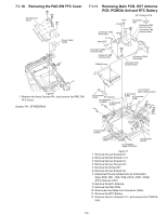
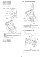
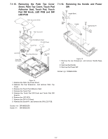
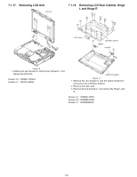
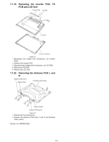
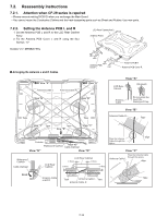
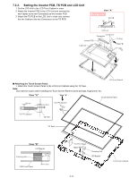
Screws : DFHM5054XA Screws :DFHE5025XA Screws :DFHE5025XA Screws : DRQT2+G6FKL Screw : DRHM5104ZA Screw : DFHE5025ZA Screw : DRHM5117ZA 7.1.12. Remove the HDD Main FPC CN Spacer HDD Connector HDD Main FPC Battery Connector Batt HDD CN Angle 7.1.13. Removing the TP PCB Connector CN801 Connector CN800 Connector CN803 TP PBC to Connector (CN801) to Connector (CN800) to Connector (CN803) Figure 11 1. Disconnect the three cables from three Connectors. (CN800, CN801, CN803) 2. Remove the two Screws, and remove the TP PCB. Screws : DRHM0002ZA 7.1.14. Removing the IO PCB 1. Remove the Screws, and remove the Batt HDD CN Angle. 2. Remove the Screw, the two Screws and the two Screws. 3. Remove the HDD Main FPC. Screw : DFHE5092ZA Screw : DFHE5025ZA Screws : DRHM5104ZA Screws : DFHE5025XA IO PCB Figure 12 1. Remove the six Screws, and remove the IO PCB. Screws : DFHE5058ZB 7-6
-
 1
1 -
2
-
3
-
4
-
5
-
6
-
7
-
8
-
9
-
10
-
11
-
12
-
13
-
14
-
15
-
16
-
17
-
18
-
 19
19 -
 20
20 -
 21
21 -
 22
22 -
 23
23 -
 24
24 -
 25
25 -
 26
26 -
 27
27 -
 28
28 -
 29
29 -
30
-
31
-
32
-
33
-
34
-
35
-
36
-
37
-
38
-
39
-
40
-
41
-
42
-
43
-
44
-
45
-
46
-
47
-
48
-
49
-
50
-
51
-
52
-
53
-
54
-
55
-
56
-
57
-
58
-
59
-
60
-
61
-
62
-
63
-
64
-
65
-
66
-
67
-
68
-
69
-
70
-
71
-
72
-
73
-
74
-
75
-
76
-
77
-
78
-
79
-
80
-
81
-
82
-
83
-
84
-
85
-
86
-
87
-
88
-
89
-
90
-
91
-
92
-
93
-
94
-
95
-
96
-
97
-
98
-
99
-
100
-
101
-
102
-
103
-
104
 |
 |
