Panasonic CF-29CRKGZKM Service Manual - Page 45
View C, Setting the Main PCB
 |
UPC - 092281833422
View all Panasonic CF-29CRKGZKM manuals
Add to My Manuals
Save this manual to your list of manuals |
Page 45 highlights
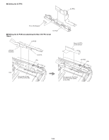
n Setting the Main PCB 1. Set the Main PCB to the Top Cabinet in order. Confirm that the Pin of the Top Cabinet of the hole of the Main PCB. View "C" Safety Working Pass the Power SW Cable through the upper side of Cable. Power SW Cable 2 Cable View "B" Safety Working Pull out the LAN Cable View "A" Main PCB Tip of the Screw Tip of the Screw Confirm that the Pin of the Top Cabinet of the hole of the Main PCB. 1 Hole MP CN Spacer Hole View "B" Batt HDD CN Angle View "A" Safety Working Main PCB Confirm that the Boss of the Top Cabinet of the hole of the Batt HDD CN Angle. Cable View "C" LAN Cable Clamper Slot Clamper Confirm that the tying point of the LAN Cable's Clamper is in the opposite direction to Main PCB. Tying point Slot Pass the LAN Cable through this Slot. LAN Cable 7-27
-
 1
1 -
2
-
3
-
4
-
5
-
6
-
7
-
8
-
9
-
10
-
11
-
12
-
13
-
14
-
15
-
16
-
17
-
18
-
19
-
20
-
21
-
22
-
23
-
24
-
25
-
26
-
27
-
28
-
29
-
30
-
31
-
32
-
33
-
34
-
35
-
36
-
37
-
38
-
39
-
 40
40 -
 41
41 -
 42
42 -
 43
43 -
 44
44 -
 45
45 -
 46
46 -
 47
47 -
 48
48 -
 49
49 -
 50
50 -
51
-
52
-
53
-
54
-
55
-
56
-
57
-
58
-
59
-
60
-
61
-
62
-
63
-
64
-
65
-
66
-
67
-
68
-
69
-
70
-
71
-
72
-
73
-
74
-
75
-
76
-
77
-
78
-
79
-
80
-
81
-
82
-
83
-
84
-
85
-
86
-
87
-
88
-
89
-
90
-
91
-
92
-
93
-
94
-
95
-
96
-
97
-
98
-
99
-
100
-
101
-
102
-
103
-
104
 |
 |
