Panasonic CF-29CRKGZKM Service Manual - Page 37
Safety Working, Arranging the SW LED PCB
 |
UPC - 092281833422
View all Panasonic CF-29CRKGZKM manuals
Add to My Manuals
Save this manual to your list of manuals |
Page 37 highlights
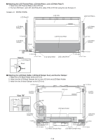
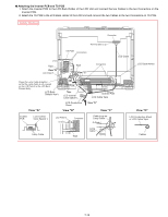
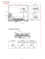
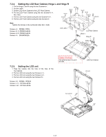
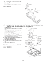
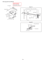
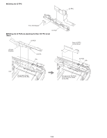
n Arranging the SW LED PCB 1. Attach the Power SW PCB Cushion and the two Tape CPU to the PW LED PCB. Power SW PCB Cushion 1±1mm 0~0.5mm 0.5±0.5mm 0~0.5mm PW LED PCB Component side 2. Bend the PW LED PCB as shown. Safety Working Bend 180 1 1±1mm 2±2mm Foil side Tape CPU PW LED PCB White line PW LED PCB Bend 180 2 PW LED PCB White line 3. Connect the Power SW Cable to the Connector on the PW LED PCB. Safety Working Power SW Cable Connector PW LED PCB 7-19
-
 1
1 -
2
-
3
-
4
-
5
-
6
-
7
-
8
-
9
-
10
-
11
-
12
-
13
-
14
-
15
-
16
-
17
-
18
-
19
-
20
-
21
-
22
-
23
-
24
-
25
-
26
-
27
-
28
-
29
-
30
-
31
-
 32
32 -
 33
33 -
 34
34 -
 35
35 -
 36
36 -
 37
37 -
 38
38 -
 39
39 -
 40
40 -
 41
41 -
 42
42 -
43
-
44
-
45
-
46
-
47
-
48
-
49
-
50
-
51
-
52
-
53
-
54
-
55
-
56
-
57
-
58
-
59
-
60
-
61
-
62
-
63
-
64
-
65
-
66
-
67
-
68
-
69
-
70
-
71
-
72
-
73
-
74
-
75
-
76
-
77
-
78
-
79
-
80
-
81
-
82
-
83
-
84
-
85
-
86
-
87
-
88
-
89
-
90
-
91
-
92
-
93
-
94
-
95
-
96
-
97
-
98
-
99
-
100
-
101
-
102
-
103
-
104
 |
 |

7-19
n
Arranging the SW LED PCB
1. Attach the Power SW PCB Cushion and the two Tape CPU to the PW LED PCB.
2. Bend the PW LED PCB as shown.
3. Connect the Power SW Cable to the Connector on the PW LED PCB.
0~0.5mm
Component side
0~0.5mm
0.5–0.5mm
1–1mm
2–2mm
1–1mm
Foil side
PW LED PCB
PW LED PCB
Power SW PCB Cushion
Tape CPU
PW LED PCB
PW LED PCB
White line
White line
1
2
Bend
180
Bend
180
Safety Working
PW LED PCB
Connector
Power SW Cable
Safety Working