Panasonic CF-29CRKGZKM Service Manual - Page 25
Pad SW Knob, LED PCB and SW, Sheet, Palm Top Cover, Touch Pad
 |
UPC - 092281833422
View all Panasonic CF-29CRKGZKM manuals
Add to My Manuals
Save this manual to your list of manuals |
Page 25 highlights
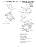
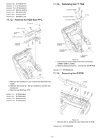
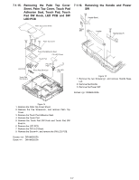
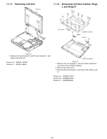
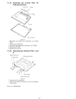
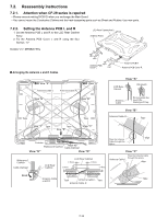
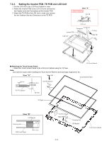
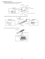
7.1.15. Removing the Palm Top Cover Sheet, Palm Top Cover, Touch Pad Adhesion Seat, Touch Pad, Touch Pad SW Knob, LED PCB and SW LED PCB 7.1.16. Removing the Handle and Power SW Handle Base L Palm Top Cover Sheet Palm Top Cover Power SW Handle Handle Base R LED PCB Touch Pad SW Knob In Touch Pad Adhesion Seat PW LED Sheet Touch Pad PW LED PCB Touch Pad SW Knob SW LED PCB Figure 15 1. Remove the two Screws, and remove Handle Base L,R. 2. Remove the Handle. 3. Remove the Power SW. Screws : DRSB4+8FKL Figure 14 1. Remove the Palm Top Cover Sheet. 2. Remove the five Screws, and remove Palm Top Cover. 3. Remove the Touch Pad Adhesion Seat. 4. Remove the Touch Pad. 5. Remove the Touch Pad SW Knob and Touch Pad SW Knob In. 6. Remove the LED PCB. 7. Remove the PW LED Sheet. 8. Remove the Screw, and remove the SW LCD PCB. Screws : DRHM0002ZA Screw : DRHM0002ZA 7-7
-
 1
1 -
2
-
3
-
4
-
5
-
6
-
7
-
8
-
9
-
10
-
11
-
12
-
13
-
14
-
15
-
16
-
17
-
18
-
19
-
 20
20 -
 21
21 -
 22
22 -
 23
23 -
 24
24 -
 25
25 -
 26
26 -
 27
27 -
 28
28 -
 29
29 -
 30
30 -
31
-
32
-
33
-
34
-
35
-
36
-
37
-
38
-
39
-
40
-
41
-
42
-
43
-
44
-
45
-
46
-
47
-
48
-
49
-
50
-
51
-
52
-
53
-
54
-
55
-
56
-
57
-
58
-
59
-
60
-
61
-
62
-
63
-
64
-
65
-
66
-
67
-
68
-
69
-
70
-
71
-
72
-
73
-
74
-
75
-
76
-
77
-
78
-
79
-
80
-
81
-
82
-
83
-
84
-
85
-
86
-
87
-
88
-
89
-
90
-
91
-
92
-
93
-
94
-
95
-
96
-
97
-
98
-
99
-
100
-
101
-
102
-
103
-
104
 |
 |
