Panasonic CF-29CRKGZKM Service Manual - Page 22
Removing the Speaker, Removing the Wireless Module and, SD PCB
 |
UPC - 092281833422
View all Panasonic CF-29CRKGZKM manuals
Add to My Manuals
Save this manual to your list of manuals |
Page 22 highlights
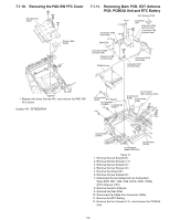
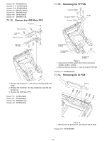
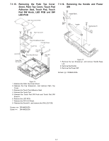
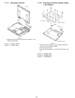
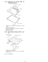
7.1.8. Removing the Speaker Heat Pipe Unit Bottom LCD Lamp Sheet Coil Cooling Sheet LAN Heat Plate MP Eject BOUSUI Plate MP Eject Spring MP Eject Lever MP Eject Slide Ass'y Speaker Angle Speaker 7.1.9. Removing the Wireless Module and SD PCB MINI PCI Protector Sheet SD PCB to Connector (CN56) CD Edge Sheet to Connector (CN2) to Connector (CN952) Wireless Module Connector CN2 Main PCB Connector CN??? Bottom Cover Figure 7 1. Remove the LCD Lamp 2. Remove the four Screws, and remove the LAN Heat Plate, Speaker Angle and the Speaker. 3. Remove the two Screws, and remove the Heat Pipe Unit Bottom. 4. Remove the four Screws, and remove the MP Eject Lever. 5. Remove the Screw, and remove the MP Eject BOUSUI Plate and MP Eject Slide Ass'y. Screws : DXQT26+D4NLT Screws : DXYN+J6FNL Screws : DXYN26+F5NLT Screw : DXQT26+D4NLT Figure 8 1. Disconnect the Cable from Connector (CN2). 2. Remove the Wireless Module. 3. Remove the MINI PCI Protector Sheet and the CD Edge Sheet. 4. Remove the three Screws. 5. Disconnect the Cable from Connector (CN56). 6. Remove the SD PCB. Screws : DFHE5025XA 7-4
-
 1
1 -
2
-
3
-
4
-
5
-
6
-
7
-
8
-
9
-
10
-
11
-
12
-
13
-
14
-
15
-
16
-
 17
17 -
 18
18 -
 19
19 -
 20
20 -
 21
21 -
 22
22 -
 23
23 -
 24
24 -
 25
25 -
 26
26 -
 27
27 -
28
-
29
-
30
-
31
-
32
-
33
-
34
-
35
-
36
-
37
-
38
-
39
-
40
-
41
-
42
-
43
-
44
-
45
-
46
-
47
-
48
-
49
-
50
-
51
-
52
-
53
-
54
-
55
-
56
-
57
-
58
-
59
-
60
-
61
-
62
-
63
-
64
-
65
-
66
-
67
-
68
-
69
-
70
-
71
-
72
-
73
-
74
-
75
-
76
-
77
-
78
-
79
-
80
-
81
-
82
-
83
-
84
-
85
-
86
-
87
-
88
-
89
-
90
-
91
-
92
-
93
-
94
-
95
-
96
-
97
-
98
-
99
-
100
-
101
-
102
-
103
-
104
 |
 |
