Panasonic PT-D4000U Operating Instructions - Page 13
Side-mounted, connection terminals
 |
UPC - 791871111529
View all Panasonic PT-D4000U manuals
Add to My Manuals
Save this manual to your list of manuals |
Page 13 highlights
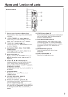
Side-mounted connection terminals R/PR G/Y B/PB SYNC/HD VD VIDEO IN S-VIDEO IN REMOTE 1 IN OUT RGB 1 IN REMOTE 2 IN RGB 2 IN IN SERIAL OUT DVI-D IN LAN VIDEO IN terminal (page 21) An input terminal for video signals. (BNC) S-VIDEO IN terminal (page 21) An input terminal for S-Video signals. (MIN4-pin DIN) This terminal complies with S1 signals and automatically toggles between 16:9 and 4:3 according to the size of input signals. RGB 1 input (RGB 1 IN) terminal (page 21) A terminal to input RGB or YPBPR signals. (BNC) RGB 2 input (RGB 2 IN) terminal (page 21) A terminal to input RGB or YPBPR signals. (D-Sub 15-pin female) DVI-D IN terminal (page 21) DVI-D signals are applied to this terminal. (24-pin DVI-D connector) LAN terminal (page 37) This terminal is used to control the projector from the PC. (10BASE-T/100BASE-TX compliant) LAN terminal (10BASE-T/100BASE-TX) Connect LAN cable. LAN 10/100 lamp (Yellow) Lights up when 100BASE-TX connected. LAN LINK/ACT lamp (Green) Lights up when connected. Flashes when receiving/sending signals. REMOTE1 lN/OUT terminal (page 15) When two or more main units are used in the system, they can be connected and controlled with M3 stereo mini jack cable available in the market. REMOTE2 IN terminal (page 49) The user can remotely control the main unit by using an external control circuit to this terminal. (D-Sub 9-pin female) SERIAL IN terminal (pages 23, 48) Use the RS-232C serial terminal as an alternative interface for controlling the projector from your PC. (D-Sub 9-pin female) SERIAL OUT terminal (pages 23, 48) The signal applied to the serial input terminal appears at this terminal. (D-Sub 9-pin male) 13
-
 1
1 -
2
-
3
-
4
-
5
-
6
-
7
-
 8
8 -
 9
9 -
 10
10 -
 11
11 -
 12
12 -
 13
13 -
 14
14 -
 15
15 -
 16
16 -
 17
17 -
 18
18 -
19
-
20
-
21
-
22
-
23
-
24
-
25
-
26
-
27
-
28
-
29
-
30
-
31
-
32
-
33
-
34
-
35
-
36
-
37
-
38
-
39
-
40
-
41
-
42
-
43
-
44
-
45
-
46
-
47
-
48
-
49
-
50
-
51
-
52
-
53
-
54
-
55
-
56
-
57
-
58
-
59
-
60
-
61
-
62
-
63
-
64
-
65
-
66
-
67
-
68
 |
 |
