Panasonic PT-D4000U Operating Instructions - Page 21
Example of connecting with PCs, Example of connecting with AV products
 |
UPC - 791871111529
View all Panasonic PT-D4000U manuals
Add to My Manuals
Save this manual to your list of manuals |
Page 21 highlights
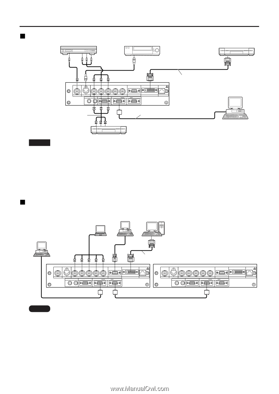
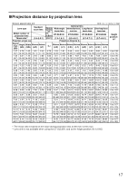
Example of connecting with AV products DVD player Video deck DVD player Digital Hi-vision video deck with DVI/HDMI terminal R/PR G/Y B/PB SYNC/HD VD VIDEO IN S-VIDEO IN REMOTE 1 IN OUT RGB 1 IN REMOTE 2 IN RGB 2 IN IN SERIAL OUT DVI-D IN LAN DVI-D Cable or HDMI-DVI conversion cable (available in the market) Control PC Red (Connect PR) Blue (Connect PB) Green(Connect Y) D-Sub 9-pin straight cable Digital Hi-vision video deck Attention • When connecting with a video deck, be sure to use the one with a built-in time base corrector (TBC) or use a TBC between the projector and the video deck. • If nonstandard burst signals are connected, the image may be distorted. If this is the case, connect a TBC between the projector and the video deck. • The EDID settings may be needed depending on the equipment connected when DVI-D signals are input. (Refer to page 33.) Example of connecting with PCs PC with PC DVI-D terminal PC Control PC R/PR G/Y B/PB SYNC/HD VD VIDEO IN S-VIDEO IN REMOTE 1 IN OUT RGB 1 IN REMOTE 2 IN RGB 2 IN IN SERIAL OUT DVI-D Cable (available in the market) DVI-D IN LAN R/PR G/Y B/PB SYNC/HD VD VIDEO IN S-VIDEO IN REMOTE 1 IN OUT RGB 1 IN REMOTE 2 IN RGB 2 IN IN SERIAL OUT DVI-D IN LAN Note • For the specifications of the RGB signals that can be applied from the PC, see the data sheet on page 58. • If your PC has the resume feature (last memory), the computer may not function properly until the resume capability is disabled. • When the SYNC ON GREEN signal is input, do not input sync signals to the SYNC/HD and VD terminals. • The EDID settings may be needed depending on the equipment connected when DVI-D signals are input. (Refer to page 33.) 21
-
 1
1 -
2
-
3
-
4
-
5
-
6
-
7
-
8
-
9
-
10
-
11
-
12
-
13
-
14
-
15
-
 16
16 -
 17
17 -
 18
18 -
 19
19 -
 20
20 -
 21
21 -
 22
22 -
 23
23 -
 24
24 -
 25
25 -
 26
26 -
27
-
28
-
29
-
30
-
31
-
32
-
33
-
34
-
35
-
36
-
37
-
38
-
39
-
40
-
41
-
42
-
43
-
44
-
45
-
46
-
47
-
48
-
49
-
50
-
51
-
52
-
53
-
54
-
55
-
56
-
57
-
58
-
59
-
60
-
61
-
62
-
63
-
64
-
65
-
66
-
67
-
68
 |
 |