Panasonic PT-D4000U Operating Instructions - Page 16
Installation - ceiling mount
 |
UPC - 791871111529
View all Panasonic PT-D4000U manuals
Add to My Manuals
Save this manual to your list of manuals |
Page 16 highlights
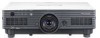
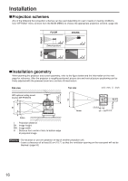
Installation Projection schemes Any of the following four projection schemes can be used depending on user's needs or viewing conditions. Use "OPTION2" menu (chosen from the MAIN MENU) to choose the appropriate projection scheme. (page 34) FLOOR CEILING FRONT (Default position) ;Installation geometry When planning the projector and screen geometry, refer to the figure below and the information on the next page for reference. After the projector is roughly positioned, picture size and vertical picture positioning can be finely adjusted with the powered zoom lens and lens tilt mechanism. REAR Side view Top view unit : mm, ( ) : inch SH 417-497 (16.4-19.6) SW With optional ceiling mount bracket (ET-PKD56H) ; ;H L 185 256 (7.3) (10.1) L H Screen L : Projection distance SH : Image height SW : Image width ;H : Distance from center of lens to bottom edge L Screen 100 (3.9) 200 (7.9) 100 (3.9) 200 (7.9) of projected image. Attention • Do not place or use one projector on top of another projection unit. • Leave a clearance of at least 50 cm (19.7") so that the ventilation opening on the rear panel will not be blocked. (page 59) 16
-
 1
1 -
2
-
3
-
4
-
5
-
6
-
7
-
8
-
9
-
10
-
 11
11 -
 12
12 -
 13
13 -
 14
14 -
 15
15 -
 16
16 -
 17
17 -
 18
18 -
 19
19 -
 20
20 -
 21
21 -
22
-
23
-
24
-
25
-
26
-
27
-
28
-
29
-
30
-
31
-
32
-
33
-
34
-
35
-
36
-
37
-
38
-
39
-
40
-
41
-
42
-
43
-
44
-
45
-
46
-
47
-
48
-
49
-
50
-
51
-
52
-
53
-
54
-
55
-
56
-
57
-
58
-
59
-
60
-
61
-
62
-
63
-
64
-
65
-
66
-
67
-
68
 |
 |