Panasonic PT-D4000U Operating Instructions - Page 29
Adjusting the position
 |
UPC - 791871111529
View all Panasonic PT-D4000U manuals
Add to My Manuals
Save this manual to your list of manuals |
Page 29 highlights
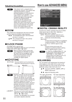
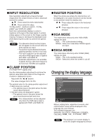
SHARPNESS "SHARPNESS" is used to adjust the crispness of the image. : Sharpens the edge of the image. : Softens the edge of the image. NOISE REDUCTION In this mode, the video noise is reduced. OFF : No correction 1 : Low 2 : Middle 3 : High AI Gray scale control is exercised to suit the images, and optimal images with a clear contrast are projected. ON : AI compensation is enabled. OFF : AI compensation is disabled. SYSTEM SELECTOR Set this according to the connected signal system. (S-Video/Video terminal input signal) AUTO : This is the standard setting. The received signal system is automatically identified. AUTO NTSC NTSC4.43 PAL PAL60 SECAM PAL-N PAL-M Note • When signal deterioration or other factors prevent images from being displayed correctly with the "AUTO" setting, change the setting to match the connected signal system. (RGB1/RGB2 terminal input signals) AUTO : This is the standard setting. The received signal system is automatically identified. When VGA60/480p signals are input AUTO VGA60 YCBCR 480pRGB When other than VGA60/480p are input AUTO RGB YPBPR (YCBCR) For the signals which are supported, refer to page 58. Adjusting the position POSITION SHIFT ASPECT ZOOM CLOCK PHASE KEYSTONE 4:3 +16 MENU SELECT SUB MENU SHIFT The position where the images are displayed can be moved here. : The position is moved horizontally. : The position is moved vertically. ASPECT AUTO : (For S-Video/Video signals only) At this setting, when S1 video signals*1 are identified as being input to the S-Video connector or video ID signals are identified as being input to the video connector, the images are displayed after automatically being converted to the 16:9 aspect ratio. 16:9 : At this setting, when standard signals are input*2, the images are converted to the 16:9 aspect ratio and displayed. When wide-screen signals are input*3, the images are displayed with their inherent aspect ratio intact. 4:3 : At this setting, when standard signals are input*2, the images are displayed with their inherent aspect ratio intact. When widescreen signals are input*3, the input aspect ratio is displayed unchanged. S4:3 : Select this setting when using a 16:9 screen. H FIT : Pictures are displayed using all the panel pixels in the horizontal direction. When a signal has an aspect ratio taller than that of the panel pixel*4, the image will be displayed with the top and bottom portions cut off. V FIT : Pictures are displayed using all the panel pixels in the vertical direction. When a signal has an aspect ratio wider than that of the panel pixel*4, the image will be displayed with the left and right sides cut off. HV FIT : The image is displayed on all the panel pixels*4. When the aspect ratio of the input signal is different from that of the panel pixel*4, the signal is transformed to the aspect ratio of the panel pixel*4 and then displayed. *1 S1 video signals are 16:9 video signals to which is added the detection signal output from the video deck or other unit which supports the wide-screen format. *2 Here, the standard signal means 4:3 or 5:4 input signals. *3 Here, the wide-screen signals means 16:9, 15:9 or 15:10 input signals. *4 The panel pixel aspect ratio is 4:3. Attention • If you choose an aspect ratio that does not match the source video's aspect ratio, you will see a picture with an aspect ratio not the same as that of the original picture. Choose the appropriate aspect ratio carefully to match that of the original picture. (Continued on the next page) 29
-
 1
1 -
2
-
3
-
4
-
5
-
6
-
7
-
8
-
9
-
10
-
11
-
12
-
13
-
14
-
15
-
16
-
17
-
18
-
19
-
20
-
21
-
22
-
23
-
 24
24 -
 25
25 -
 26
26 -
 27
27 -
 28
28 -
 29
29 -
 30
30 -
 31
31 -
 32
32 -
 33
33 -
 34
34 -
35
-
36
-
37
-
38
-
39
-
40
-
41
-
42
-
43
-
44
-
45
-
46
-
47
-
48
-
49
-
50
-
51
-
52
-
53
-
54
-
55
-
56
-
57
-
58
-
59
-
60
-
61
-
62
-
63
-
64
-
65
-
66
-
67
-
68
 |
 |
