Panasonic PT-D6000ULK Operating Instructions - Page 35
Technical Information, Display dots of each model, ENGLISH - 35
 |
UPC - 791871111871
View all Panasonic PT-D6000ULK manuals
Add to My Manuals
Save this manual to your list of manuals |
Page 35 highlights
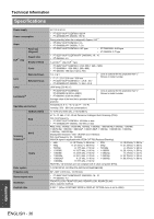
Technical Information Mode Display resolution (dots)*1 Scanning frequency H (kHz) V (Hz) Dot clock frequency (MHz) Picture quality*2 RGB2 WSXGA+ 1 920 x 1 080*10 WUXGA 1 680 x 1 050 1 920 x 1 080 1 920 x 1 200 65.3 60.0 66.6 59.9 74.0 60.0 146.3 138.5 154.0 A AA*5 AA*5 D *1. The "i" appearing after the resolution indicates an interlaced signal. *2. The following symbols are used to indicate picture quality. AA Maximum picture quality can be obtained. A Signals are converted by the image processing circuit before picture is projected. B Some loss of data occurs to make projection easier. *3. Marked signals are indicated in *4. The following symbols are used to indicate the format. V = VIDEO, S = S-VIDEO, D = DVI, R = RGB, Y = YPBPR *5. PT-DW6300U/PT-D6000U: A *6. PT-DZ6710U/PT-DZ6700U/PT-D6000U: A *7. PT-DZ6710U/PT-DZ6700U/PT-DW6300U: A *8. PT-DW6300U/PT-D6000U: B *9. RGB signals only and DVI-D is not compatible. *10.VESA CVT-RB (Reduced Blanking) compatible. PnP*3 DVI-D EIDI1 DVI-D EIDI2 D NOTE: • Projecting an interlaced signal may cause flicker in screen. J Display dots of each model Format*4 D/R PT-DZ6710U PT-DZ6700U PT-DW6300U PT-D6000U 1 920 x 1 200 1 920 x 1 200 1 280 x 800 1 024 x 768 Appendix ENGLISH - 35
-
 1
1 -
2
-
3
-
4
-
5
-
6
-
7
-
8
-
9
-
10
-
11
-
12
-
13
-
14
-
15
-
16
-
17
-
18
-
19
-
20
-
21
-
22
-
23
-
24
-
25
-
26
-
27
-
28
-
29
-
 30
30 -
 31
31 -
 32
32 -
 33
33 -
 34
34 -
 35
35 -
 36
36 -
 37
37 -
 38
38 -
 39
39 -
 40
40 -
41
-
42
-
43
-
44
-
45
-
46
-
47
-
48
-
49
-
50
 |
 |
