Panasonic VDR M70 Operating Instructions - Page 18
camera/recorder.
 |
UPC - 037988251216
View all Panasonic VDR M70 manuals
Add to My Manuals
Save this manual to your list of manuals |
Page 18 highlights
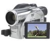
~MYY I sa • If 0 "it p 6 7 8 9 r. 10 11 14/ 1) IM (Uri:Ede the ) 13 12 113olloria 1 Infrared receiver (P.36) When the remote control is used to operate the IND video camera/recorder. fills receiver will receive the inf raw( crip 2 Lock cover and Lock button (P. 56) 3 Lock cap string attachment hole (P.34) 4 Recording indicator (R88) The red indicator will litih. dining recording. Stereo Microphone (P. 54) 6 Optical 10 x zoom lens (VDR-M70) (P.56) Optical 18x zoom lens (VDR-M70) (P.56) 7 Lens hood (P.57) Always remove this lens hood when 'Ong generally available tele-conversion or wideconversion lens. 9 Accessory shoe Accessories, such as a stereo microplrone (VW-VMS2E: optional). are attached here. 10 External microphone jack (P.67) 11 AV output jack (P.68) 12 2.5" type liquid crystal display (inside) (P.37) 13 BATTERY EJECT switch (P.41) The BA 11ERY E.D.CT switch is located on the bottom of this DVD video camera/recorder: Slide if when removing the battery. Although the external appearances of VDI-1M50 and VDH-M70 are different. the method of operating both models is ident ical. VINI-M70 i llustrations are used in this manual. 8 Zoom lever (P.56) Push the lever to the T side lor telephoto, or lo the W side for wide-angle.
-
 1
1 -
2
-
3
-
4
-
5
-
6
-
7
-
8
-
9
-
10
-
11
-
12
-
 13
13 -
 14
14 -
 15
15 -
 16
16 -
 17
17 -
 18
18 -
 19
19 -
 20
20 -
 21
21 -
 22
22 -
 23
23 -
24
-
25
-
26
-
27
-
28
-
29
-
30
-
31
-
32
-
33
-
34
-
35
-
36
-
37
-
38
-
39
-
40
-
41
-
42
-
43
-
44
-
45
-
46
-
47
-
48
-
49
-
50
-
51
-
52
-
53
-
54
-
55
-
56
-
57
-
58
-
59
-
60
-
61
-
62
-
63
-
64
-
65
-
66
-
67
-
68
-
69
-
70
-
71
-
72
-
73
-
74
-
75
-
76
-
77
-
78
-
79
-
80
-
81
-
82
-
83
-
84
-
85
-
86
-
87
-
88
-
89
-
90
-
91
-
92
-
93
-
94
-
95
-
96
-
97
-
98
-
99
-
100
-
101
-
102
-
103
-
104
-
105
-
106
-
107
-
108
-
109
-
110
-
111
-
112
-
113
-
114
-
115
-
116
-
117
-
118
-
119
-
120
-
121
-
122
-
123
-
124
-
125
-
126
-
127
-
128
-
129
-
130
-
131
-
132
-
133
-
134
-
135
-
136
-
137
-
138
-
139
-
140
-
141
-
142
-
143
-
144
-
145
-
146
-
147
-
148
-
149
-
150
-
151
-
152
-
153
-
154
-
155
-
156
-
157
-
158
-
159
-
160
-
161
-
162
 |
 |
