ProForm Fusion 6.0 Lx English Manual
ProForm Fusion 6.0 Lx Manual
 |
View all ProForm Fusion 6.0 Lx manuals
Add to My Manuals
Save this manual to your list of manuals |
ProForm Fusion 6.0 Lx manual content summary:
- ProForm Fusion 6.0 Lx | English Manual - Page 1
have questions, or if a part is damaged or missing, PLEASE CONTACT OUR CUSTOMER SERVICE DEPARTMENT DIRECTLY. CALL TOLL-FREE: 1-888-533-1333 Mon.-Fri., 6 a.m.-6 p.m. MST ON THE WEB: www.proformservice.com USER'S MANUAL CAUTION Read all precautions and instructions in this manual before using this - ProForm Fusion 6.0 Lx | English Manual - Page 2
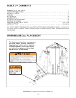
24 CABLE DIAGRAM 27 WEIGHT RESISTANCE CHART 29 EXERCISE GUIDELINES 30 ORDERING REPLACEMENT PARTS Back Cover LIMITED WARRANTY Back Cover Note: A PART IDENTIFICATION CHART and a PART LIST/EXPLODED DRAWING are attached in the center of this manual. Remove the PART IDENTIFICATION CHART and - ProForm Fusion 6.0 Lx | English Manual - Page 3
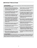
injury, read the following important precautions before using the weight system. 1. Read all instructions in this manual and all warnings on the weight system before using the weight system. Use the weight system only as described in this manual. 2. It is the responsibility of the owner to ensure - ProForm Fusion 6.0 Lx | English Manual - Page 4
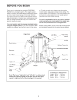
versatile PROFORM® FUSION 6.0 LX weight system. The weight system offers a selection of weight stations designed to develop every major muscle group of the body. Whether your goal is to tone your body, build dramatic muscle size and strength, or improve your cardiovascular system, the weight system - ProForm Fusion 6.0 Lx | English Manual - Page 5
? If you have questions after reading the assembly instructions, see the front cover of this manual. The Four Stages of the Assembly Process Frame Assembly-You will begin by assembling the base and the uprights that form the skeleton of the weight system. Cable Assembly-During this stage you will - ProForm Fusion 6.0 Lx | English Manual - Page 6
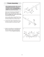
Before beginning assembly, make sure you understand the information in the box on the previous page. For help identifying small parts, use the PART IDENTIFICATION CHART in the center of this manual. 109 111 1 112 Attach the Foot Plate (90) to the Right Base (1) with an M10 x 120mm Bolt (97), two - ProForm Fusion 6.0 Lx | English Manual - Page 7
4. Attach the Center Upright (9) to the Right and 4 Left Bases (1, 2) with four M10 x 70mm Bolts (57), four M10 Washers (109), and two M10 Nylon Locknuts (111). Do not tighten the Bolts yet. 9 5. Attach the Right Upright (7) to the Right Base (1) 5 with two M10 x 90mm Bolts (102) and two - ProForm Fusion 6.0 Lx | English Manual - Page 8
6. Attach the Right Seat Upright (11) to the Right 6 Base (1) with the indicated M10 x 80mm Carriage Bolts (112) and two M10 Nylon Locknuts (111). 7. Attach the Curl Post Upright (10) to the Right 7 Base (1) with the indicated M10 x 80mm Carriage Bolts (112) and two M10 Nylon Locknuts (111). - ProForm Fusion 6.0 Lx | English Manual - Page 9
9. Attach the Left Seat Upright (14) to the Left Base 9 (2) with the indicated M10 x 80mm Carriage Bolts (112) and two M10 Nylon Locknuts (111). 111 14 111 2 112 10. Attach the Right Top Frame (3) to the Center Upright (9) with two M10 x 70mm Bolts (57), two M10 Washers (109), and an M10 - ProForm Fusion 6.0 Lx | English Manual - Page 10
with an M10 x 65mm Bolt (110), two M10 Washers (109), a 1/2" Spacer (68), and an M10 Nylon Locknut (111). Slide a Weight Bumper (66) onto the Weight Guide. 30 30 Attach the other three Weight Guides (30) to the Center Base (5) in the same manner. Tighten the M10 x 70mm Bolts (57) used in step - ProForm Fusion 6.0 Lx | English Manual - Page 11
Frames (3, 4) with four M10 x 70mm Bolts (57), four M10 Washers (109), and two M10 Nylon Locknuts (111). Do not tighten the Bolts yet. Attach a Weight Guide (30) inside the Center Top Frame (6) with an M10 x 65mm Bolt (110), two M10 Washers (109), a 1/2" Spacer (68), and an M10 Nylon Locknut (111 - ProForm Fusion 6.0 Lx | English Manual - Page 12
18. Apply grease to the 1 3/4" Bushing (64). Attach 18 the Military Press Frame (20) and the 1 3/4" Bushing inside the Left Upright (8) with an M10 x 63mm Bolt (104) and an M10 Nylon Locknut (111). 19. Apply grease to an M10 x 45mm Bolt (95). Attach 19 the Military Press Arm (21) to the - ProForm Fusion 6.0 Lx | English Manual - Page 13
22. Apply grease to an M10 x 70mm Bolt (57). Attach 22 a Press Arm Handle (27) to the Left Press Arm (25) with the Bolt and an M10 Nylon Locknut (111). Do not overtighten the Locknut; the Press Arm Handle must be able to pivot easily. Repeat this step with the other Press Arm Handle (27) and - ProForm Fusion 6.0 Lx | English Manual - Page 14
26. Wrap the Butterfly Cable (73) around a Pulley 26 (43). Attach the Pulley, a Cable Trap (48), an M10 Washer (109), and two Finger Guards (45) to the Left Butterfly Arm (22) with an M10 x 50mm Bolt (106) and an M10 Nylon Locknut (111). Make sure that the Cable Trap is oriented to hold the - ProForm Fusion 6.0 Lx | English Manual - Page 15
30. Wrap the Butterfly Cable (73) over a Pulley (43). 30 Attach the Pulley to the Right Top Frame (3) with an M10 x 40mm Bolt (116) and an M10 Nylon Locknut (111). Repeat this step with another Pulley (43). 111 43 73 3 43 116 31. Wrap the Butterfly Cable (73) under a Pulley (43). 31 - ProForm Fusion 6.0 Lx | English Manual - Page 16
34. Attach the Butterfly Cable (73) and a Weight Cap 34 (67) to the indicated Weight Tube (75) with an M10 x 50mm Bolt (106) and an M10 Nylon Locknut (111). 73 111 67 106 75 35. Locate the Low Cable (70). - ProForm Fusion 6.0 Lx | English Manual - Page 17
38. Wrap the Low Cable (70) over a Pulley (43). 38 Attach the Pulley, a Cable Trap (48), and two Half Finger Guards (46) at the bottom hole of the pair of Pulley Plates (49) with an M10 x 50mm Bolt (106) and an M10 Nylon Locknut (111). Makes sure that the Cable Trap is oriented to hold the - ProForm Fusion 6.0 Lx | English Manual - Page 18
43. Route the High Cable (88) up through the Left Top Frame (4) and over a Small Pulley (84). Attach the Pulley inside the Top Frame with an M10 x 65mm Bolt (110), two M10 Washers (109), two 1/2" Spacers (68), and an M10 Nylon Locknut (111). 43 109 68 110 84 88 111 109 68 4 44. Route the High - ProForm Fusion 6.0 Lx | English Manual - Page 19
48. Attach the High Cable (88) and a Weight Cap 48 (67) to the indicated Weight Tube (75) with an M10 x 50mm Bolt (106) and an M10 Nylon Locknut (111). 49. Locate the Press Cable (72). Attach the Cable to 49 - ProForm Fusion 6.0 Lx | English Manual - Page 20
53. Wrap the Press Cable (72) under a Pulley (43). 53 Attach the Pulley, a Cable Trap (48), an M10 Washer (109), and two Half Finger Guards (46) to the Left Base (2) with an M10 x 130mm Bolt (107) and an M10 Nylon Locknut (111). Make sure that the Cable Trap is oriented to hold the Cable in - ProForm Fusion 6.0 Lx | English Manual - Page 21
57. Orient the Shroud Frame (89) with the indicated 57 slot near the top. Attach the Right and Left Shrouds (32, 86) to the Shroud Frame with twelve M4 x 13mm Self-tapping Screws (105). 32 Slot 86 105 105 105 105 105 105 105 105 58. Attach the Shroud Frame (89) to the Center Top 58 - ProForm Fusion 6.0 Lx | English Manual - Page 22
59. Attach the Left Shroud (86) to the Left Upright (8) 59 with six M4 x 13mm Self-tapping Screws (105). Attach the Right Shroud (32) to the Right Upright (7) in the same manner. 7 60. Attach a Backrest (35) to the Backrest Frame (19) with four M6 x 25mm Screws (99). 32 60 99 19 99 105 105 - ProForm Fusion 6.0 Lx | English Manual - Page 23
62. Attach the Small Seat (36) to the Left Seat Frame 62 (18) with two M6 x 25mm Screws (99), an M6 x 85mm Screw (98), and an M6 Washer (114). Attach the Large Seat (not shown) to the Right Seat Frame (not shown) in the same manner. 63. Tighten an Adjustment Knob (69) into the Left 63 Seat - ProForm Fusion 6.0 Lx | English Manual - Page 24
get the most benefit from your exercise program. Also, refer to the accompanying exercise guide to see the correct form for each exercise. Make sure all parts are properly tightened each time the weight system is used. Replace any worn parts immediately. The weight system can be cleaned with a damp - ProForm Fusion 6.0 Lx | English Manual - Page 25
height with an Adjustment Knob (69). Remove the Curl Pad (38) from the weight system when performing an exercise that does not require it. LOCKING THE WEIGHT STACK Lock a weight stack by inserting a Lock Pin (78) through a Weight Guide (30) and securing the Lock (77) onto the Lock Pin. 35 69 19 - ProForm Fusion 6.0 Lx | English Manual - Page 26
station, engage the Leg Lever Lock (47) onto the Leg Lever (15) tube. TIGHTENING THE CABLES A Woven cable, the type of cable used on the weight system, can stretch slightly when it is first used. If there is slack in the cables before resistance is felt, the cables should be tightened. To - ProForm Fusion 6.0 Lx | English Manual - Page 27
make sure that the cables, the cable traps, and the finger guards have been assembled correctly. If the cables have not been correctly routed, the weight system will not function properly and damage may occur. The numbers show the correct route for each cable. Make sure that the cable traps do not - ProForm Fusion 6.0 Lx | English Manual - Page 28
2 4 5 High Cable (88) 7 Length: 13' 4 3/4" 8 1 6 3 6 5 9 Press Cable (72) Length: 11' 6" 4 1 3 2 28 - ProForm Fusion 6.0 Lx | English Manual - Page 29
the approximate weight resistance at each exercise station. The numbers refer to the 12.5 lb. weight plates. Weight resistance at each station may vary due to differences in individual weight plates as well as friction between the cables, pulleys, and weight guides. WEIGHT 1 2 3 4 5 6 7 8 9 10 - ProForm Fusion 6.0 Lx | English Manual - Page 30
full range of motion for each exercise, and moving only the appropriate parts of the body. Exercising in an uncontrolled manner will leave you feeling exhausted. On the exercise guide accompanying this manual you will find photographs showing the correct form for several exercises, and a list of the - ProForm Fusion 6.0 Lx | English Manual - Page 31
work- out. • Rest for 30 seconds after each set for a weight loss workout. Plan to spend the first couple of weeks familiarizing yourself with the equipment and learning the proper form for each exercise. COOLING DOWN End each workout with 5 to 10 minutes of stretching. Include stretches for both - ProForm Fusion 6.0 Lx | English Manual - Page 32
in assembly. The number in parentheses by each drawing is the key number of the part, from the PART LIST in the center of this manual. Note: Some small parts may have been pre-attached. If a part is not in the parts bag, check to see if it has been pre-attached. M6 Washer (114) M4 - ProForm Fusion 6.0 Lx | English Manual - Page 33
M10 x 65mm Bolt (110) M10 x 70mm Bolt (57) M10 x 75mm Bolt (96) M10 x 80mm Carriage Bolt (112) M6 x 85mm Screw (98) M10 x 90mm Bolt (102) M10 x 95mm Bolt (108) M10 x 100mm Bolt (85) M10 x 120mm Bolt (97) M10 x 130mm Bolt (107) M10 x 150mm Bolt (94) - ProForm Fusion 6.0 Lx | English Manual - Page 34
PART LIST-Model No. PFSY5015.0 R1005A Key Qty. No. 11 21 31 41 51 61 71 81 91 10 1 11 Press Arm Press Arm Handle 1 3/4" Square Inner Cap Leg Press Plate Weight Guide Top Cover Right Shroud Right Bottom Cover Weight Backrest Small Seat Large Seat Curl Pad Foam Pad Upright Bushing Upright Cover - ProForm Fusion 6.0 Lx | English Manual - Page 35
35mm Screw Key Qty. No. 114 3 115 2 116 2 #1 #1 #1 #2 Description M6 Washer M10 x 55mm Button Bolt M10 x 40mm Bolt User's Manual Exercise Guide Allen Wrench Grease Pack Note: "#" indicates a non-illustrated part. Specifications are subject to change without notice. See the back cover of the user - ProForm Fusion 6.0 Lx | English Manual - Page 36
EXPLODED DRAWING A-Model No. PFSY5015.0 23 55 111 43 55 61 45 48 109 45 110 85 71 106 61 113 111 91 51 24 85 61 111 45 83 111 44 45 45 48 43 111 109 46 45 43 48 55 46 109 71 61 106 22 91 109 97 35 54 R1005A 109 102 92 73 101 94 99 38 37 55 99 16 53 52 39 15 58 111 43 - ProForm Fusion 6.0 Lx | English Manual - Page 37
EXPLODED DRAWING B-Model No. PFSY5015.0 R1005A 111 46 46 49 48 43 49 46 48 43 106 46 102 111 111 46 95 46 43 111 109 20 60 64 60 55 111 95 55 59 42 104 111 103 114 106 50 46 48 109 43 46 72 69 100 21 59 41 42 55 59 59 100 55 99 54 35 28 19 8 99 54 111 80 102 46 - ProForm Fusion 6.0 Lx | English Manual - Page 38
EXPLODED DRAWING C-Model No. PFSY5015.0 R1005A 111 111 109 109 111 6 31 105 32 68 105 105 109 111 109 110 111 109 110 43 95 43 95 31 105 73 111 68 68 105 88 111 68 105 67 67 106 106 105 34 109 34 105 115 86 89 30 30 105 105 30 105 105 77 75 30 75 77 105 105 - ProForm Fusion 6.0 Lx | English Manual - Page 39
EXPLODED DRAWING D-Model No. PFSY5015.0 R1005A 57 109 111 3 57 109 111 111 43 43 95 43 116 51 57 109 43 84 68 109 111 68 109 110 109 111 111 57 109 111 95 43 43 111 68 4 68 109 109 110 88 9 57 109 57 109 55 111 56 27 59 57 62 100 42 59 25 74 56 42 59 42 59 51 45 - ProForm Fusion 6.0 Lx | English Manual - Page 40
PROFORM FUSION 6.0 LX weight system) • the SERIAL NUMBER of the product (see the front cover of this manual) • the KEY NUMBER and DESCRIPTION of the part(s) (see the PART a service center, freight charges to and from the service center will be the customer's responsibility. For in-home service, the
-
 1
1 -
 2
2 -
 3
3 -
 4
4 -
 5
5 -
 6
6 -
 7
7 -
8
-
9
-
10
-
11
-
12
-
13
-
14
-
15
-
16
-
17
-
18
-
19
-
20
-
21
-
22
-
23
-
24
-
25
-
26
-
27
-
28
-
29
-
30
-
31
-
32
-
33
-
34
-
35
-
36
-
37
-
38
-
39
-
40
 |
 |
Visit our website at
www.proform.com
new products, prizes,
fitness tips, and much more!
CAUTION
Read all precautions and instruc-
tions in this manual before using
this equipment. Save this manual
for future reference.
Model No. PFSY5015.0
Serial No.
Write the serial number in the
space above for future reference.
Serial Number Decal (Under Seat)
QUESTIONS?
As a manufacturer, we are com-
mitted to providing complete
customer satisfaction. If you
have questions, or if a part is
damaged or missing, PLEASE
CONTACT OUR CUSTOMER
SERVICE DEPARTMENT
DIRECTLY.
CALL TOLL-FREE:
1-888-533-1333
Mon.–Fri., 6 a.m.–6 p.m. MST
ON THE WEB:
www.proformservice.com
USER’S MANUAL