Sony KDL-40SL140 Operating Instructions - Page 10
Installation Dimensions Table, Screw and Hook Locations Diagram, Screw location, Hook location - model
 |
UPC - 027242248960
View all Sony KDL-40SL140 manuals
Add to My Manuals
Save this manual to your list of manuals |
Page 10 highlights
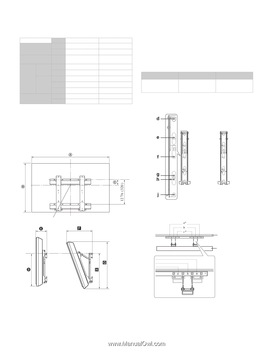
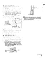
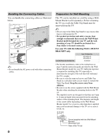
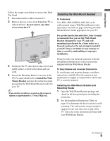
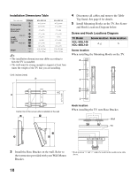
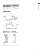
Installation Dimensions Table Unit: inches (mm) TV dimensions TV Model A B Screen center dimensions C D Angle (0°) Length E for each F mounting angle Angle (20°) G H TV Weight x4 KDL-40SL140 44 1/8 (1,119) 24 1/4 (615) 4 7/8 (122) 17 1/4 (438) 6 3/4 (171) 14 (354) 23 1/8 (587) 18 3/4 (476) 43 lb. (19.5 kg) 172 lb. (78 kg) KDL-46SL140 49 3/8 (1,252) 27 1/4 (691) 3 3/8 (84) 17 1/4 (437) 7 (176) 15 1/4 (385) 26 (659) 18 7/8 (477) 57 lb. (25,5 kg) 228 lb. (102 kg) ~ • The installation dimensions may differ according to how the TV is installed. • The wall must be strong enough to support at least four times the weight of the TV that you are installing. 4 Disconnect all cables and remove the Table- Top Stand. See page 8 for details. 5 Install Mounting Hooks on the TV. See Screw and Hook Locations Diagram below. Screw and Hook Locations Diagram TV Model Screw location Hook location KDL-40SL140 KDL-46SL140 d, g b Screw location When installing the Mounting Hooks on the TV. Unit: inches (mm) Center line of the screen when installed on the wall Hook location When installing the TV onto Base Bracket. Wall TV 3 Install the Base Bracket on the wall. Refer to the instruction provided with your Wall-Mount Bracket. * Hook position "a" and "c" cannot be used for the models in the table above. 10
-
 1
1 -
2
-
3
-
4
-
 5
5 -
 6
6 -
 7
7 -
 8
8 -
 9
9 -
 10
10 -
 11
11 -
 12
12 -
 13
13 -
 14
14 -
 15
15 -
16
-
17
-
18
-
19
-
20
-
21
-
22
-
23
-
24
-
25
-
26
-
27
-
28
-
29
-
30
-
31
-
32
-
33
-
34
-
35
-
36
-
37
-
38
-
39
-
40
-
41
-
42
-
43
-
44
-
45
-
46
-
47
-
48
 |
 |