Sony PCV-E314DS Reference Manual - Page 112
E, F, G, H, I, J, K, L, M, I/O connectors
 |
View all Sony PCV-E314DS manuals
Add to My Manuals
Save this manual to your list of manuals |
Page 112 highlights
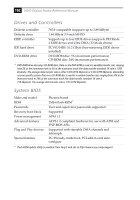
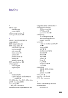
104 VAIO Digital Studio Reference Manual removing 41 display - See monitor display, power management 19 DMA channel assignments 94 drive DVD-ROM specifications 102 IDE connectors 54 installing an additional 44 specifications 102 DVD-ROM drive location of 3 performance of discs 102 specifications 102 E error messages beep codes 91 PCI configuration 92 expansion slot specifications 101 expansion slots 15 expansion slots - See Also slots F fan connectors 62 CPU 62 PS-Fan 62 fax card - See modem card fax/modem - See Also communications FCC Part 68 iv floppy drive - See diskette drive front panel removing 26 replacing 27 front panel header 50 front view 2 buttons and switches 4 connectors 5, 6 drives 3 indicators 5 G graphics controller - See graphics graphics specifications 100 H header - See front panel header I i.LINK (IEEE-1394) connector 6, 75 I/O address map 96 I/O connectors game port 12 i.LINK (IEEE-1394) 14, 75 keyboard and mouse 10 mic, line in, headphones 12 monitor 11 Optical Digital Audio Output 14, 71 printer port 11 serial port 1 10 S-Link (Control A1) 14, 71 telephone and line 13 USB ports 10, 57 I/O slot covering 43 I/O slot specifications 101 icons, description of 8 IDE connectors 54 specifications 102 input devices iii installing add-in card 30 hard disk drive 44 system memory 36 interference iii IRQ assignments 95 J jumper - See system board K keyboard connector 56 L L2 cache specifications 100 lithium battery, replacing 33 M map - See Also I/O address map
-
 1
1 -
2
-
3
-
4
-
5
-
6
-
7
-
8
-
9
-
10
-
11
-
12
-
13
-
14
-
15
-
16
-
17
-
18
-
19
-
20
-
21
-
22
-
23
-
24
-
25
-
26
-
27
-
28
-
29
-
30
-
31
-
32
-
33
-
34
-
35
-
36
-
37
-
38
-
39
-
40
-
41
-
42
-
43
-
44
-
45
-
46
-
47
-
48
-
49
-
50
-
51
-
52
-
53
-
54
-
55
-
56
-
57
-
58
-
59
-
60
-
61
-
62
-
63
-
64
-
65
-
66
-
67
-
68
-
69
-
70
-
71
-
72
-
73
-
74
-
75
-
76
-
77
-
78
-
79
-
80
-
81
-
82
-
83
-
84
-
85
-
86
-
87
-
88
-
89
-
90
-
91
-
92
-
93
-
94
-
95
-
96
-
97
-
98
-
99
-
100
-
101
-
102
-
103
-
104
-
105
-
106
-
 107
107 -
 108
108 -
 109
109 -
 110
110 -
 111
111 -
 112
112 -
 113
113 -
 114
114
 |
 |
