Sony PCV-E314DS Reference Manual - Page 57
System Board
 |
View all Sony PCV-E314DS manuals
Add to My Manuals
Save this manual to your list of manuals |
Page 57 highlights
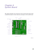
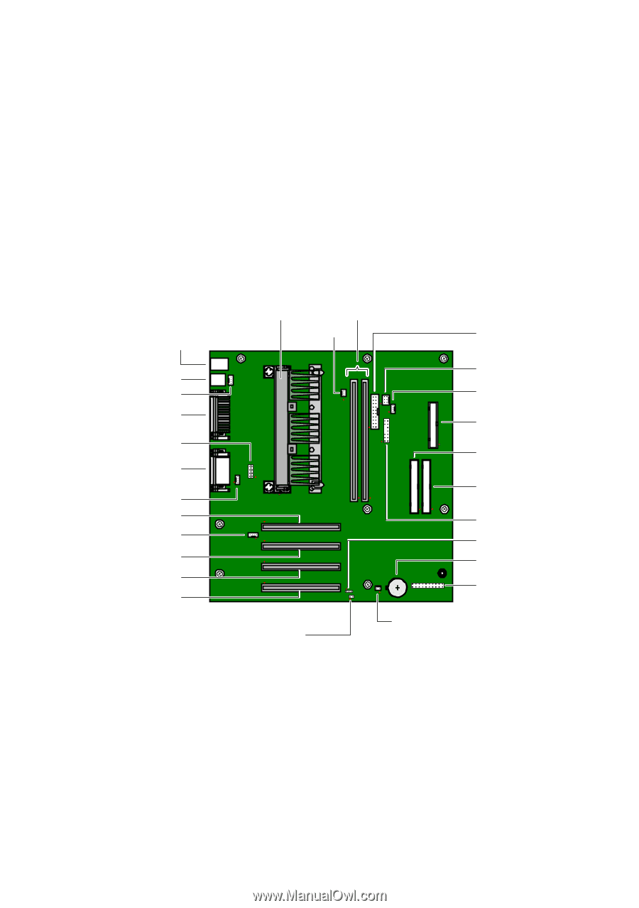
Chapter 4 System Board This chapter identifies each component on the system board and provides a detailed description of each connector and jumper on the system board. Optinal Keyboard, Mouse USB1 J8 Monitor, COM1, Printer CPU Speed Mic In, Line In, Line Out, Game CD-In Slot 1 (PCI) Modem In Slot 2 (PCI) Slot 3 (PCI) Slot 4 (PCI) Processor Memory CPU Fan (not used) Power Fan 2 Power Supply Fan Serial 2 Diskette Secondary IDE Primary IDE Optical Digital Audio Out BIOS Recovery Battery Front panel header Clear CMOS Ring (not used) OM04581.VSD 49
-
 1
1 -
2
-
3
-
4
-
5
-
6
-
7
-
8
-
9
-
10
-
11
-
12
-
13
-
14
-
15
-
16
-
17
-
18
-
19
-
20
-
21
-
22
-
23
-
24
-
25
-
26
-
27
-
28
-
29
-
30
-
31
-
32
-
33
-
34
-
35
-
36
-
37
-
38
-
39
-
40
-
41
-
42
-
43
-
44
-
45
-
46
-
47
-
48
-
49
-
50
-
51
-
 52
52 -
 53
53 -
 54
54 -
 55
55 -
 56
56 -
 57
57 -
 58
58 -
 59
59 -
 60
60 -
 61
61 -
 62
62 -
63
-
64
-
65
-
66
-
67
-
68
-
69
-
70
-
71
-
72
-
73
-
74
-
75
-
76
-
77
-
78
-
79
-
80
-
81
-
82
-
83
-
84
-
85
-
86
-
87
-
88
-
89
-
90
-
91
-
92
-
93
-
94
-
95
-
96
-
97
-
98
-
99
-
100
-
101
-
102
-
103
-
104
-
105
-
106
-
107
-
108
-
109
-
110
-
111
-
112
-
113
-
114
 |
 |
49
Chapter 4
System Board
This chapter identifies each component on the system board and provides
a detailed description of each connector and jumper on the system board.
Slot 4 (PCI)
Processor
Memory
Power
Secondary IDE
Primary IDE
Battery
Fan 2
OM04581.VSD
CPU Fan
(not used)
Diskette
Optical Digital
Audio Out
Front panel header
Ring (not used)
CPU Speed
Mic In, Line In,
Line Out, Game
Monitor,
COM1, Printer
USB1
J8
BIOS Recovery
Clear CMOS
Power Supply Fan
Serial 2
CD-In
Optinal Keyboard,
Mouse
Modem In
Slot 1 (PCI)
Slot 3 (PCI)
Slot 2 (PCI)