Sony STR DA2400ES Service Manual - Page 101
Micon Board, Ic8003, F2602e-01-tr Xm Receiver
 |
UPC - 027242729872
View all Sony STR DA2400ES manuals
Add to My Manuals
Save this manual to your list of manuals |
Page 101 highlights
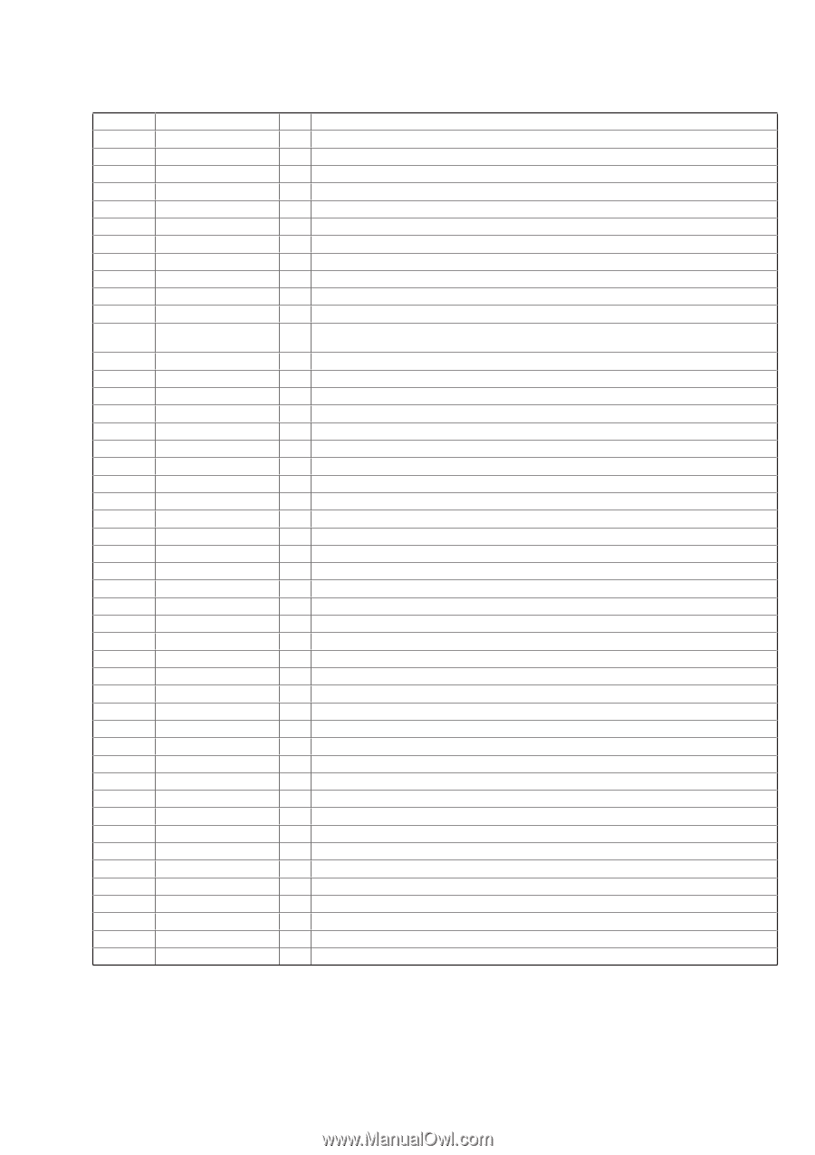
STR-DA2400ES/DG920 MICON BOARD IC8003 F2602E-01-TR (XM RECEIVER) Pin No. Pin Name I/O Description 1 LSOPTXRX - Not used 2 VSS - Ground terminal 3 SCTXOUT O Serial data output to the system controller 4 VDD - Power supply terminal (+3.3V) 5 SCRXIN I Serial data input from the system controller 6 VSS - Ground terminal 7 COMMSEL I Command mode selection signal input terminal Not used 8 VDD - Power supply terminal (+3.3V) 9 XIRQ O Interrupt request signal output terminal Not used 10 VSS - Ground terminal 11 XRESET I Reset signal input from the system controller "L": reset 12 SLAVESL I Master/slave mode selection signal input terminal "L": master mode, "H": slave mode Fixed at "L" in this set 13 COMRXDIG - Not used 14 COMTXDIG - Not used 15 COMTXEN - Not used 16 VSS - Ground terminal 17 VDD - Power supply terminal (+3.3V) 18 COMRXP I XM receiver differential signal (positive) input from the XM connector 19 COMRXM I XM receiver differential signal (negative) input from the XM connector 20 VDD - Power supply terminal (+3.3V) 21 VSS - Ground terminal 22 COMTXM O XM transmitter differential signal (negative) output to the XM connector 23 COMTXP O XM transmitter differential signal (positive) output to the XM connector 24, 25 VSS - Ground terminal 26 OSCOUT O System clock output terminal (45.1584 MHz) 27 VDD - Power supply terminal (+3.3V) 28 OSCIN I System clock input terminal (45.1584 MHz) 29 VSS - Ground terminal 30 TEST - Not used 31 VSS - Ground terminal 32 HSDPDATA - Not used 33 VDD - Power supply terminal (+3.3V) 34 HSDPCLK - Not used 35 VSS - Ground terminal 36 HSDPEN - Not used 37 I2SDATA O I2S digital audio data output to the D/A converter (for XM section) 38 VSS - Ground terminal 39 I2SSCLK O I2S bit clock signal output to the D/A converter (for XM section) 40 VDD - Power supply terminal (+3.3V) 41 I2SLRCLK O I2S L/R sampling clock signal output to the D/A converter (for XM section) 42 VSS - Ground terminal 43 I2SOCLK O I2S over sample clock signal output to the D/A converter (for XM section) 44 VSS - Ground terminal 45 SAIICLK - Not used 46 VDD - Power supply terminal (+3.3V) 47 SAIIDATA - Not used 48 SAIIEN - Not used 101
-
 1
1 -
2
-
3
-
4
-
5
-
6
-
7
-
8
-
9
-
10
-
11
-
12
-
13
-
14
-
15
-
16
-
17
-
18
-
19
-
20
-
21
-
22
-
23
-
24
-
25
-
26
-
27
-
28
-
29
-
30
-
31
-
32
-
33
-
34
-
35
-
36
-
37
-
38
-
39
-
40
-
41
-
42
-
43
-
44
-
45
-
46
-
47
-
48
-
49
-
50
-
51
-
52
-
53
-
54
-
55
-
56
-
57
-
58
-
59
-
60
-
61
-
62
-
63
-
64
-
65
-
66
-
67
-
68
-
69
-
70
-
71
-
72
-
73
-
74
-
75
-
76
-
77
-
78
-
79
-
80
-
81
-
82
-
83
-
84
-
85
-
86
-
87
-
88
-
89
-
90
-
91
-
92
-
93
-
94
-
95
-
 96
96 -
 97
97 -
 98
98 -
 99
99 -
 100
100 -
 101
101 -
 102
102 -
 103
103 -
 104
104 -
 105
105 -
 106
106 -
107
-
108
-
109
-
110
-
111
-
112
-
113
-
114
-
115
-
116
-
117
-
118
-
119
-
120
-
121
-
122
-
123
-
124
-
125
-
126
-
127
-
128
-
129
-
130
-
131
-
132
-
133
-
134
-
135
-
136
-
137
-
138
-
139
-
140
-
141
-
142
-
143
-
144
 |
 |