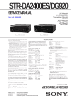
Sony STR DA2400ES Service Manual - Page 4
Servicing, Notes, General, Disassembly, Electrical, Adjustment, Diagrams, Table, Contents, Exploded - test
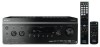 |
UPC - 027242729872
View all Sony STR DA2400ES manuals
Add to My Manuals
Save this manual to your list of manuals |
Page 4 highlights
STR-DA2400ES/DG920 TABLE OF CONTENTS 1. SERVICING NOTES 5 2. GENERAL 7 3. DISASSEMBLY 3-1. Disassembly Flow 13 3-2. Case 14 3-3. Front Panel Block (DA2400ES 14 3-4. Front Panel Block (DG920 15 3-5. Tuner (FM/AM), CIS Board and PREOUT Board ......... 15 3-6. DIGITAL VIDEO Board 16 3-7. VIDEO Board 16 3-8. Back Panel Block (DA2400ES 17 3-9. Back Panel Block (DG920 17 3-10. MICON Board, DIGITAL Board 18 3-11. ACLASS Board 18 3-12. Main Block 19 3-13. MAIN Board 19 4. TEST MODE 20 5. ELECTRICAL ADJUSTMENT 24 6. DIAGRAMS 6-1. Block Diagram - DIGITAL AUDIO/TUNER Section 27 6-2. Block Diagram - DSP/XM Section 28 6-3. Block Diagram - ANALOG AUDIO Section 29 6-4. Block Diagram - AMP Section 30 6-5. Block Diagram - HDMI Section 31 6-6. Block Diagram - VIDEO (1/2) Section 32 6-7. Block Diagram - VIDEO (2/2)/PANEL Section 33 6-8. Block Diagram - POWER SUPPLY Section 34 6-9. Printed Wiring Board - DIGITAL Board (Component Side 36 6-10. Printed Wiring Board - DIGITAL Board (Conductor Side 37 6-11. Schematic Diagram - DIGITAL Board (1/2 38 6-12. Schematic Diagram - DIGITAL Board (2/2 39 6-13. Printed Wiring Board - DIGITAL VIDEO Board (Component Side 40 6-14. Printed Wiring Board - DIGITAL VIDEO Board (Conductor Side 41 6-15. Schematic Diagram - DIGITAL VIDEO Board (1/4 42 6-16. Schematic Diagram - DIGITAL VIDEO Board (2/4 43 6-17. Schematic Diagram - DIGITAL VIDEO Board (3/4 44 6-18. Schematic Diagram - DIGITAL VIDEO Board (4/4 45 6-19. Printed Wiring Board - MAIN Board 46 6-20. Schematic Diagram - MAIN Board (1/3 47 6-21. Schematic Diagram - MAIN Board (2/3 48 6-22. Schematic Diagram - MAIN Board (3/3 49 6-23. Printed Wiring Board - ACLASS Board 50 6-24. Schematic Diagram - ACLASS Board 51 6-25. Printed Wiring Board - VIDEO Board 52 6-26. Schematic Diagram - VIDEO Board 53 6-27. Printed Wiring Board - DSP Board 54 6-28. Schematic Diagram - DSP Board 55 6-29. Printed Wiring Board - MICON Board (Component Side 56 6-30. Printed Wiring Board - MICON Board (Conductor Side 57 6-31. Schematic Diagram - MICON Board (1/3 58 6-32. Schematic Diagram - MICON Board (2/3 59 6-33. Schematic Diagram - MICON Board (3/3 60 6-34. Printed Wiring Board - LIMITER Board 61 6-35. Schematic Diagram - LIMITER Board 61 6-36. Printed Wiring Boards - CONNECTOR Section 62 6-37. Schematic Diagram - CONNECTOR Section 63 6-38. Printed Wiring Board - DISPLAY Board 64 6-39. Schematic Diagram - DISPLAY Board 65 6-40. Printed Wiring Boards - PANEL Section 66 6-41. Schematic Diagram - PANEL Section 67 6-42. Printed Wiring Board - SURR SPEAKER Board - ........ 68 6-43. Schematic Diagram - SURR SPEAKER Board 69 6-44. Printed Wiring Board - CIS Board (DA2400ES: US model 70 6-45. Schematic Diagram - CIS Board (DA2400ES: US model 71 6-46. Printed Wiring Board - PREOUT Board (DA2400ES: AEP, ECE, UK models 72 6-47. Schematic Diagram - PREOUT Board (DA2400ES: AEP, ECE, UK models 72 6-48. Printed Wiring Board - DCDC CON Board 73 6-49. Schematic Diagram - DCDC CON Board 73 6-50. Printed Wiring Boards - POWER Section 74 6-51. Schematic Diagram - POWER Section 75 7. EXPLODED VIEWS 7-1. Case Section 105 7-2. Front Panel Section (DA2400ES 106 7-3. Front Panel Section (DG920 107 7-4. DIGITAL VIDEO Board Section 108 7-5. Back Panel Section 109 7-6. Chassis Section 110 8. ELECTRICAL PARTS LIST 111 Accessories are given in the last of the electrical parts list. • Abbreviation ECE : Continental European, East European and Russian models 4
-
 1
1 -
 2
2 -
 3
3 -
 4
4 -
 5
5 -
 6
6 -
 7
7 -
 8
8 -
 9
9 -
 10
10 -
11
-
12
-
13
-
14
-
15
-
16
-
17
-
18
-
19
-
20
-
21
-
22
-
23
-
24
-
25
-
26
-
27
-
28
-
29
-
30
-
31
-
32
-
33
-
34
-
35
-
36
-
37
-
38
-
39
-
40
-
41
-
42
-
43
-
44
-
45
-
46
-
47
-
48
-
49
-
50
-
51
-
52
-
53
-
54
-
55
-
56
-
57
-
58
-
59
-
60
-
61
-
62
-
63
-
64
-
65
-
66
-
67
-
68
-
69
-
70
-
71
-
72
-
73
-
74
-
75
-
76
-
77
-
78
-
79
-
80
-
81
-
82
-
83
-
84
-
85
-
86
-
87
-
88
-
89
-
90
-
91
-
92
-
93
-
94
-
95
-
96
-
97
-
98
-
99
-
100
-
101
-
102
-
103
-
104
-
105
-
106
-
107
-
108
-
109
-
110
-
111
-
112
-
113
-
114
-
115
-
116
-
117
-
118
-
119
-
120
-
121
-
122
-
123
-
124
-
125
-
126
-
127
-
128
-
129
-
130
-
131
-
132
-
133
-
134
-
135
-
136
-
137
-
138
-
139
-
140
-
141
-
142
-
143
-
144
 |
 |
