Sony STR DA2400ES Service Manual - Page 92
Digital Video Board, Ic3601, Fli8638-lf Video Processor
 |
UPC - 027242729872
View all Sony STR DA2400ES manuals
Add to My Manuals
Save this manual to your list of manuals |
Page 92 highlights
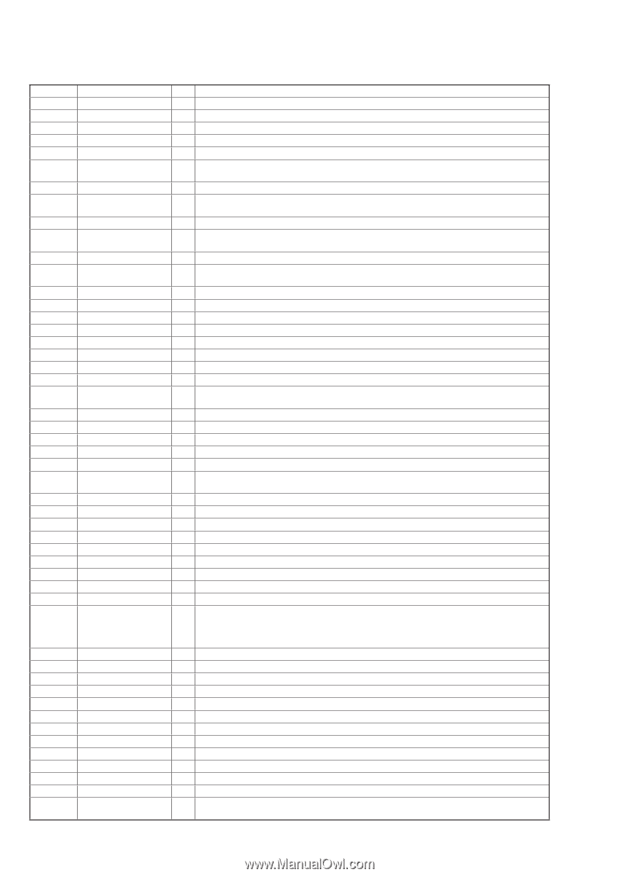
STR-DA2400ES/DG920 DIGITAL VIDEO BOARD IC3601 FLI8638-LF (VIDEO PROCESSOR) Pin No. Pin Name I/O Description A1 NC - Not used A2 MSTR1_SDA O Power detection signal output to the system controller A3 MSTR1_SCL O Busy signal output to the system controller A4, A5 FSDATA1, FSDATA3 I/O Two-way data bus with the SD-RAM A6 FSDQM0 O Data mask signal output to the SD-RAM (upper byte) A7 to A10 FSDATA5, FSDATA7, FSDATA9, FSDATA11 I/O Two-way data bus with the SD-RAM A11 FSDQM1 O Data mask signal output to the SD-RAM (lower byte) A12, A13 FSDATA13, FSDATA15 I/O Two-way data bus with the SD-RAM A14 VDDA18_DLL - Power supply terminal (+1.8V) A15, A16 FSDATA17, FSDATA19 I/O Two-way data bus with the SD-RAM A17 FSDQS2 O Data strobe signal output to the SD-RAM (upper byte) A18 to A21 FSDATA21, FSDATA23, FSDATA25, FSDATA27 I/O Two-way data bus with the SD-RAM A22 FSDQS3 O Data strobe signal output to the SD-RAM (lower byte) A23, A24 FSDATA29, FSDATA31 I/O Two-way data bus with the SD-RAM A25, A26 RPLL_AGND - Ground terminal B1 BDATA0 I Digital video (blue) signal input terminal Not used B2 OCM_UDO_1 O UART communication transfer data output to the system controller B3 OCM_UDI_1 I UART communication transfer data input from the system controller B4, B5 FSDATA0, FSDATA2 I/O Two-way data bus with the SD-RAM B6 FSDQS0 O Data strobe signal output to the SD-RAM (upper byte) B7 to B10 FSDATA4, FSDATA6, FSDATA8, FSDATA10 I/O Two-way data bus with the SD-RAM B11 FSDQS1 O Data strobe signal output to the SD-RAM (lower byte) B12, B13 FSDATA12, FSDATA14 I/O Two-way data bus with the SD-RAM B14 VSSA18_DLL - Ground terminal B15, B16 FSDATA16, FSDATA18 I/O Two-way data bus with the SD-RAM B17 FSDQM2 O Data mask signal output to the SD-RAM (upper byte) B18 to B21 FSDATA20, FSDATA22, FSDATA24, FSDATA26 I/O Two-way data bus with the SD-RAM B22 FSDQM3 O Data mask signal output to the SD-RAM (lower byte) B23, B24 FSDATA28, FSDATA30 I/O Two-way data bus with the SD-RAM B25 RPLL_DGND - Ground terminal B26 XTAL O System clock output terminal (19.6608 MHz) C1 to C3 BDATA3 to BDATA1 I Digital video (blue) signal input terminal Not used C4 FSCKE O Clock enable signal output to the SD-RAM C5 FSCLKN O Clock signal (negative) output to the SD-RAM C6 to C8 FSADDR8 to FSADDR6 O Address signal output to the SD-RAM C9 FSVREF O Reference voltage output to the SD-RAM C10 to C18 FSADDR5, FSADDR12, FSADDR9, FSADDR4, FSADDR11, FSADDR3 O to FSADDR0 Address signal output to the SD-RAM C19 FSVREF O Reference voltage output to the SD-RAM C20, C21 FSBKSEL1, FSBKSEL0 O Bank select signal output to the SD-RAM C22 FSCS1 O Chip select signal output terminal Not used C23 FSWE O Write enable signal output to the SD-RAM C24 FSRAS O Row address strobe signal output to the SD-RAM C25 RPLL_1.8V - Power supply terminal (+1.8V) C26 TCLK I System clock input terminal (19.6608 MHz) D1 to D3 BDATA6 to BDATA4 I Digital video (blue) signal input terminal Not used D4 DDR_2.5V - Power supply terminal (+2.5V) D5 FSCLKP O Clock signal (positive) output to the SD-RAM D6 to D8 DDR_2.5V - Power supply terminal (+2.5V) D9 FSVREFVSS - Ground terminal D10 to D15 DDR_2.5V - Power supply terminal (+2.5V) 92
-
 1
1 -
2
-
3
-
4
-
5
-
6
-
7
-
8
-
9
-
10
-
11
-
12
-
13
-
14
-
15
-
16
-
17
-
18
-
19
-
20
-
21
-
22
-
23
-
24
-
25
-
26
-
27
-
28
-
29
-
30
-
31
-
32
-
33
-
34
-
35
-
36
-
37
-
38
-
39
-
40
-
41
-
42
-
43
-
44
-
45
-
46
-
47
-
48
-
49
-
50
-
51
-
52
-
53
-
54
-
55
-
56
-
57
-
58
-
59
-
60
-
61
-
62
-
63
-
64
-
65
-
66
-
67
-
68
-
69
-
70
-
71
-
72
-
73
-
74
-
75
-
76
-
77
-
78
-
79
-
80
-
81
-
82
-
83
-
84
-
85
-
86
-
 87
87 -
 88
88 -
 89
89 -
 90
90 -
 91
91 -
 92
92 -
 93
93 -
 94
94 -
 95
95 -
 96
96 -
 97
97 -
98
-
99
-
100
-
101
-
102
-
103
-
104
-
105
-
106
-
107
-
108
-
109
-
110
-
111
-
112
-
113
-
114
-
115
-
116
-
117
-
118
-
119
-
120
-
121
-
122
-
123
-
124
-
125
-
126
-
127
-
128
-
129
-
130
-
131
-
132
-
133
-
134
-
135
-
136
-
137
-
138
-
139
-
140
-
141
-
142
-
143
-
144
 |
 |