Sony VPL-HW20 Operating Instructions - Page 74
Preset memory numbers for each input signal, Analog signal, Digital signal, Signal
 |
View all Sony VPL-HW20 manuals
Add to My Manuals
Save this manual to your list of manuals |
Page 74 highlights
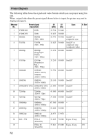
Preset memory numbers for each input signal Analog signal Signal Video signal (VIDEO INPUT and S VIDEO INPUT connectors) Component signal (INPUT A and Y PB/CB PR/ CR connectors) Video GBR signal (INPUT A connector) Computer signal (INPUT A connector) Digital signal Preset memory number 1, 2 3 to 11 3 to 11 21 to 39, 55 to 56 Signal Component signal (HDMI 1, 2 connectors) Video GBR signal (HDMI 1, 2 connectors) Computer signal (HDMI 1, 2 connectors) Preset memory number 3 to 8, 10 to 14 3 to 8, 10 to 14 10 to 13*, 26, 32, 36, 37, 45, 47, 50, 55 * Some digital signals input from computers may be displayed as preset memory number of Component or Video GBR signal. 74
-
 1
1 -
2
-
3
-
4
-
5
-
6
-
7
-
8
-
9
-
10
-
11
-
12
-
13
-
14
-
15
-
16
-
17
-
18
-
19
-
20
-
21
-
22
-
23
-
24
-
25
-
26
-
27
-
28
-
29
-
30
-
31
-
32
-
33
-
34
-
35
-
36
-
37
-
38
-
39
-
40
-
41
-
42
-
43
-
44
-
45
-
46
-
47
-
48
-
49
-
50
-
51
-
52
-
53
-
54
-
55
-
56
-
57
-
58
-
59
-
60
-
61
-
62
-
63
-
64
-
65
-
66
-
67
-
68
-
 69
69 -
 70
70 -
 71
71 -
 72
72 -
 73
73 -
 74
74 -
 75
75 -
 76
76 -
 77
77 -
 78
78 -
 79
79 -
80
-
81
-
82
-
83
 |
 |

74
Preset memory numbers for each input signal
Analog signal
Digital signal
* Some digital signals input from computers may be displayed as preset memory number of
Component or Video GBR signal.
Signal
Preset memory number
Video signal (VIDEO INPUT and
S VIDEO INPUT connectors)
1, 2
Component signal (INPUT A and Y P
B
/C
B
P
R
/
C
R
connectors)
3 to 11
Video GBR signal (INPUT A connector)
3 to 11
Computer signal (INPUT A connector)
21 to 39, 55 to 56
Signal
Preset memory number
Component signal (HDMI 1, 2 connectors)
3 to 8, 10 to 14
Video GBR signal (HDMI 1, 2 connectors)
3 to 8, 10 to 14
Computer signal (HDMI 1, 2 connectors)
10 to 13*, 26, 32, 36, 37, 45, 47,
50, 55