Stihl FS 460 C-EM Product Instruction Manual - Page 20
FS 460 C-M, FS 460 C-M L
 |
View all Stihl FS 460 C-EM manuals
Add to My Manuals
Save this manual to your list of manuals |
Page 20 highlights
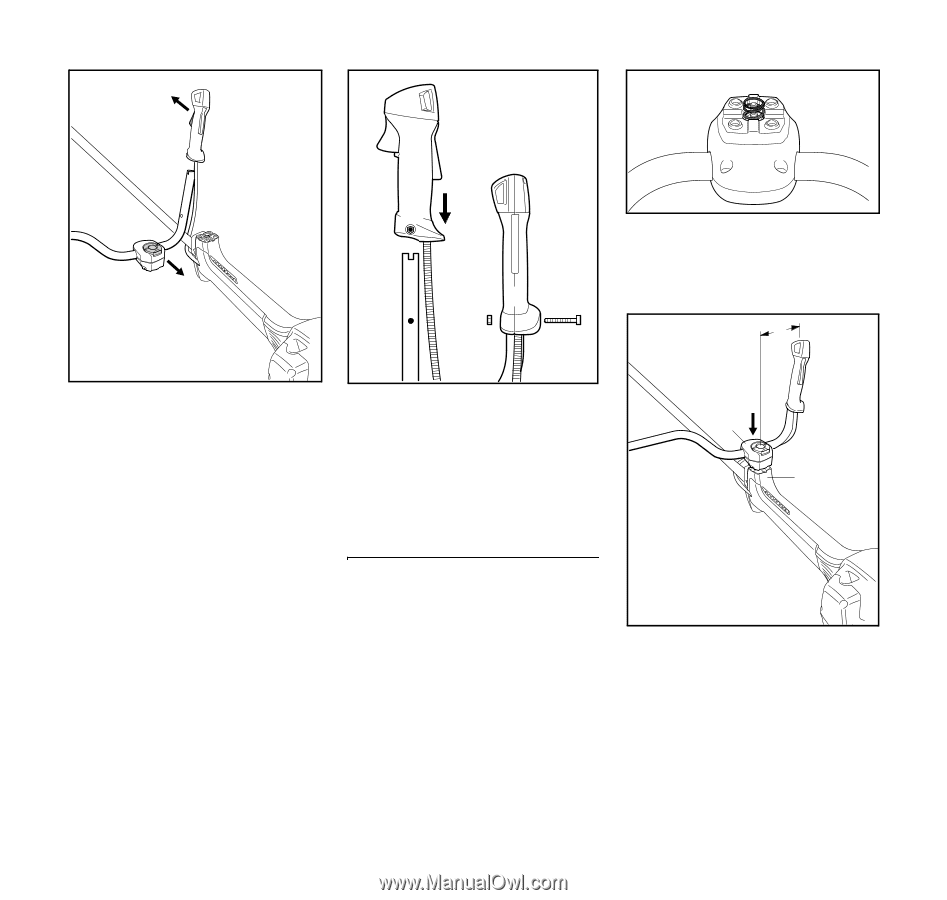
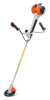
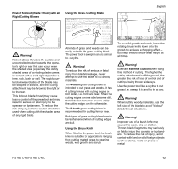
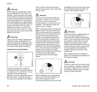
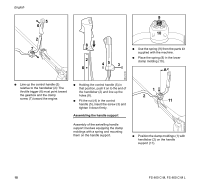
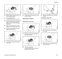
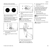
6BA001 KN English 5 6 2 7 9 10 8 N Use the spring (9) from the parts kit supplied with the machine. 2 45 3 N Place the spring (9) in the lower clamp molding (10). 8 A 6BA002 KN 6BA019 KN N Line up the control handle (5) relative to the handlebar (2): The throttle trigger (6) must point toward the gearbox and the clamp screw (7) toward the engine. N Holding the control handle (5) in that position, push it on to the end of the handlebar (2) and line up the holes (8). N Fit the nut (4) in the control handle (5), insert the screw (3) and tighten it down firmly. Assembling the handle support 1 2 11 Assembly of the swivelling handle support involves equipping the clamp moldings with a spring and mounting them on the handle support. N Position the clamp moldings (1) with handlebar (2) on the handle support (11). 6BA020 KN 18 FS 460 C-M, FS 460 C-M L
-
 1
1 -
2
-
3
-
4
-
5
-
6
-
7
-
8
-
9
-
10
-
11
-
12
-
13
-
14
-
 15
15 -
 16
16 -
 17
17 -
 18
18 -
 19
19 -
 20
20 -
 21
21 -
 22
22 -
 23
23 -
 24
24 -
 25
25 -
26
-
27
-
28
-
29
-
30
-
31
-
32
-
33
-
34
-
35
-
36
-
37
-
38
-
39
-
40
-
41
-
42
-
43
-
44
-
45
-
46
-
47
-
48
-
49
-
50
-
51
-
52
-
53
-
54
-
55
-
56
-
57
-
58
-
59
-
60
-
61
-
62
-
63
-
64
-
65
-
66
-
67
-
68
-
69
-
70
-
71
-
72
-
73
-
74
-
75
-
76
-
77
-
78
-
79
-
80
-
81
-
82
-
83
-
84
-
85
-
86
-
87
-
88
-
89
-
90
-
91
-
92
-
93
-
94
-
95
-
96
-
97
-
98
-
99
-
100
-
101
-
102
-
103
-
104
 |
 |