Stihl FS 460 C-EM Product Instruction Manual - Page 21
Adjusting the handlebar, Opening the wing screw, Closing the wing screw
 |
View all Stihl FS 460 C-EM manuals
Add to My Manuals
Save this manual to your list of manuals |
Page 21 highlights
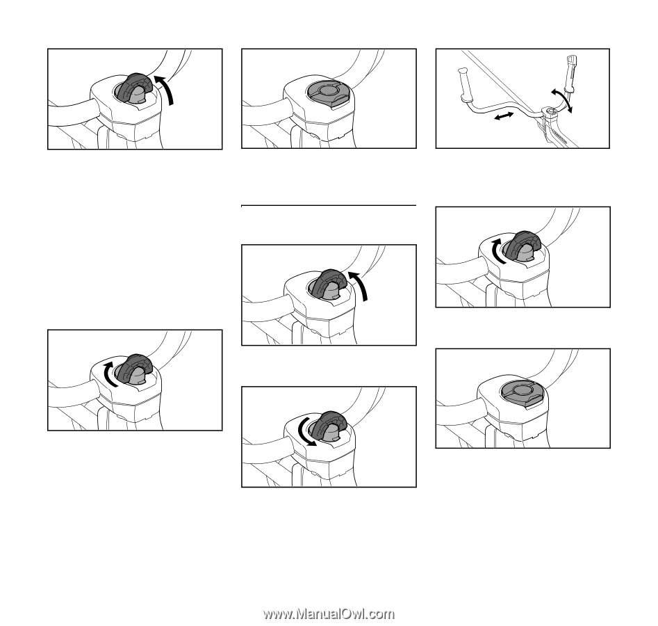
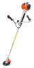
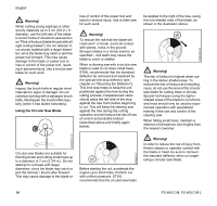
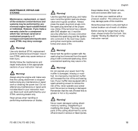
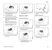
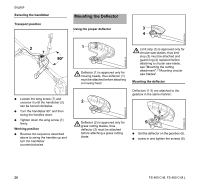
English 7 2 6BA007 KN 6BA006 KN 6BA003 KN N Raise the grip of the wing screw (7) to the upright position. N Turn the wing screw counterclockwise as far as stop. N Push the wing screw into the handle support as far as stop and then screw it down - but do not finally tighten yet. N Adjust the handlebar (2) so that distance A is no more than 15 cm. N Line up the handlebar at a right angle to the drive tube. N Fold the grip of the wing screw down so that it is flush. Adjusting the handlebar Opening the wing screw N Raise the grip of the wing screw to the upright position. 6BA023 KN N Move the handlebar to the required position. Closing the wing screw N Turn the wing screw clockwise as far as stop. 6BA005 KN 6BA005 KN 6BA006 KN N Turn the wing screw clockwise as far as stop. N Turn the wing screw counterclockwise until the handle support can be moved. 6BA004 KN N Fold the grip of the wing screw down so that it is flush. FS 460 C-M, FS 460 C-M L 19
-
 1
1 -
2
-
3
-
4
-
5
-
6
-
7
-
8
-
9
-
10
-
11
-
12
-
13
-
14
-
15
-
 16
16 -
 17
17 -
 18
18 -
 19
19 -
 20
20 -
 21
21 -
 22
22 -
 23
23 -
 24
24 -
 25
25 -
 26
26 -
27
-
28
-
29
-
30
-
31
-
32
-
33
-
34
-
35
-
36
-
37
-
38
-
39
-
40
-
41
-
42
-
43
-
44
-
45
-
46
-
47
-
48
-
49
-
50
-
51
-
52
-
53
-
54
-
55
-
56
-
57
-
58
-
59
-
60
-
61
-
62
-
63
-
64
-
65
-
66
-
67
-
68
-
69
-
70
-
71
-
72
-
73
-
74
-
75
-
76
-
77
-
78
-
79
-
80
-
81
-
82
-
83
-
84
-
85
-
86
-
87
-
88
-
89
-
90
-
91
-
92
-
93
-
94
-
95
-
96
-
97
-
98
-
99
-
100
-
101
-
102
-
103
-
104
 |
 |