Thermador VCIN36JP Installation Instructions
Thermador VCIN36JP Manual
 |
View all Thermador VCIN36JP manuals
Add to My Manuals
Save this manual to your list of manuals |
Thermador VCIN36JP manual content summary:
- Thermador VCIN36JP | Installation Instructions - Page 1
INSTALLATION MANUAL For THERMADOR PROFESSIONAL® Custom Insert MANUEL D'INSTALLATION Pour hottes encastrées sur mesure PROFESSIONALmc de THERMADOR MANUAL DE INSTALACIÓN Para campanas empotradas a medida PROFESSIONAL® de THERMADOR Models/ Modèles/ Modelos: VCIN36JP VCIN48JP VCIN54JP VCIB36JP VCIB48JP - Thermador VCIN36JP | Installation Instructions - Page 2
the Correct Blower 10 Installation Instructions 11 Blower Motor Installation 11 Remote Installation (optional 15 VCIN Model Installation 18 VCIB Model Installation 26 Installing Filters, Filter Spacers, & Grease Trays 28 Service 29 Before Calling Service 29 Product Data Rating Plate - Thermador VCIN36JP | Installation Instructions - Page 3
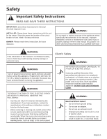
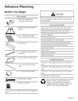
or fuse. Mark it for easy reference. OWNER: Please retain these instructions for future reference. WARNING: Do not repair or replace any part of the appliance unless specifically recommended in the manuals. Improper installation, service or maintenance can cause injury or property damage. Refer to - Thermador VCIN36JP | Installation Instructions - Page 4
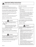
Cooking Ranges It is the responsibility of the owner and the installer to determine if additional requirements and/or standards apply to specific installations. be vented to the outdoors. Do not vent exhaust air into spaces within walls, ceilings, attics, crawl spaces or garages. • When cutting or - Thermador VCIN36JP | Installation Instructions - Page 5
- 36" Custom Hood Liner (VCIN models only) LINER248 - 48" Custom Hood Liner (VCIN models only) LINER254 - 54" Custom Hood Liner (VCIN models only) VCI2REMKS - Remote Control Remove all tape and packaging before using the appliance. Please, recycle the packaging material, as all THERMADOR® appliance - Thermador VCIN36JP | Installation Instructions - Page 6
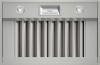
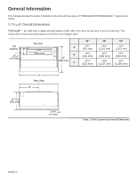
Information This manual provides the proper installation instructions for two styles of THERMADOR PROFESSIONAL® custom insert hoods: VCINxxJP Overall Dimensions VCINxxJP - 22" (559 mm) in depth and with widths of 33¾" (857 mm), 45¾" (1,162 mm) or 51¾" (1,315 mm). This model series features brushed - Thermador VCIN36JP | Installation Instructions - Page 7
41½" (1,054 mm), 52½" (1,334 mm) or 58½" (1,486 mm). This model series features brushed stainless-steel filters, halogen lights, hood liner, and a 1000CFM integral blower. 15/8" (42mm) 45/16" (110 mm) Top View 21¾" (553 mm) A B 24¾" (629 mm) C 36 po 40½" (1,029 mm) 163/16" (411 mm) 32Ǫ" (822 mm - Thermador VCIN36JP | Installation Instructions - Page 8
if a THERMADOR PROFESSIONAL® series range or rangetop is operated with multiple burners at high settings under a hood that is installed at minimum clearances. Unit Weight When calculating the load for the housing support system, be sure to consider the weight of the ventilation unit. Model Weight - Thermador VCIN36JP | Installation Instructions - Page 9
installations. For safety reasons, ducting should vent directly outdoors (not into an attic, underneath the house, into the garage or into any enclosed space). The unit cannot be used in conjunction with a recirculation unit. If using a 10" (254 mm) duct, THERMADOR best delivery. Hoods are supplied - Thermador VCIN36JP | Installation Instructions - Page 10
6 2 7 2 8 2 N/A 20 3¼" x 10" to Round 10 1 7" Inline Backdraft 7 Damper 3¼" x 10" Roof Jack N/A and Shutter NOTE: These commonly used installation parts can be purchased at a local hardware store. THERMADOR® does not manufacture all these parts. Table 4: Duct Lengths English 8 - Thermador VCIN36JP | Installation Instructions - Page 11
x2 1213/16" (325 mm) 3 5/16" (84 mm) 17½" (445 mm) Figure 2: Transition Dimensions 4 5/16" (502 mm) 21¾" (552 mm) 11¼" (286 mm) 17½" (444 mm) hood. 4. Fasten transition to hood using two (2) 1" (25.4 mm) sheet metal screws included with hood. 5. Seal connection between transition and hood - Thermador VCIN36JP | Installation Instructions - Page 12
into an outlet that is properly installed and grounded. WARNING: The appliance must be grounded. Choosing the Correct Blower A variety of interior and exterior blower options (Remote, Inline or Integral) are available for THERMADOR PROFESSIONAL® custom insert series hoods. If the unit you have - Thermador VCIN36JP | Installation Instructions - Page 13
Installation Instructions Blower Motor Installation BLOWER Integral Blower 600 CFM Integral Blower 1000 CFM Integral blower installation only 1. The blower is attached to the hood using weld studs provided on the mounting plate. Figure 5 exhibits the weld stud locations. 2. Guide the motor - Thermador VCIN36JP | Installation Instructions - Page 14
mm) 25" (635 mm) Figure 6: Integral Blower Model VTN1030C From Blower Integral Blower models VTN630C and VTN1030C are integrated into the hood at the time of installation (VCIN models). For complete installation instructions see the instructions supplied with the blower unit. 1. Remove junction - Thermador VCIN36JP | Installation Instructions - Page 15
10" (527 mm) (254 mm) 19 7/8" (505 mm) Figure 8: VTR1330E Remote Blower Custom insert models can be installed with remote blowers (VCIN models). For complete installation instructions see the instructions supplied with the blower unit. 1. Remove junction box channel covering the wires (see Figure - Thermador VCIN36JP | Installation Instructions - Page 16
Wiring the Hood with an Inline Blower Both VCIN and VCIB custom insert models can be installed with inline blowers. For complete installation instructions see the instructions supplied with the blower unit. 12 1/8" (308 mm) 12 " (305 mm) 7/8" (22 mm) ø 9 7/8" (251 mm) 19 1/8" (486 mm) 13/4" ( - Thermador VCIN36JP | Installation Instructions - Page 17
optional) NOTE: When using the Custom Insert with remote the unit loses the "AUTO" function and the over-temperature heat sensor described in the Use & Care Guide. It is recommended that the Remote Control be wired to the hood after the hood is installed. 1. Access wiring a) Remove filters, spacers - Thermador VCIN36JP | Installation Instructions - Page 18
extension harness to the connector inside the junction box. Figure 16: Relay Board Hookup Figure 17: Pigtail Remote Connection 3. Prepare wall or similar surface for installation as shown below in Figure 18. 1½" (40 mm) 15/16" (23 mm) 11/16" (17 mm) 2¾" (69 mm) 11¾" (298 mm) 3/16" (5 mm) 11 - Thermador VCIN36JP | Installation Instructions - Page 19
4. Connect remote control to extension harness with the included 30 ft (914.4 cm) cable. 5. Insert remote control into cutout. Secure from behind with two (2) nuts onto the weld studs. 6. Reinstall hood components from Figure 12 and Figure 13. Figure 19: Remote Install English 17 - Thermador VCIN36JP | Installation Instructions - Page 20
See "Installation Preparation" on page 6 for suggestions on determining hood height. When calculating the load for the housing support system, be sure to include the weight of the ventilation unit. See Table 3 on page 6 for unit weight by model. Build housing in accordance with the dimensions noted - Thermador VCIN36JP | Installation Instructions - Page 21
Model A VCIN36JP 32 15/16" (836 mm) VCIN48JP 44 15/16" (1,141 mm) VCIN54JP 50 15/16" (1,294 mm) B 21¼" (540 mm) 21¼" (540 mm) 21¼" (540 mm) B A Figure 21: VCIN Cutout Dimensions To be placed on 16" (407 mm) stud centers 2⅛" (54 mm) 1½" x 3½" x 12⅛" (38 x 89 x 308 mm) 1½" x 3½" x 44½" (38 - Thermador VCIN36JP | Installation Instructions - Page 22
A B A 1½" x 3½" x 2713/16" (38 x 89 x 707 mm) B ǫ" (16 mm) C 1½" x 3½" x 23Ǫ" (38 x 89 x 594 mm) C Figure 23: VCIN Stud Dimensions English 20 3" (76 mm) 12¼" (311 mm) 26 5/16" (668 mm) Figure 24: VCIN Side View - Thermador VCIN36JP | Installation Instructions - Page 23
a) Refer to "Choosing the Correct Blower" on page 10. b) Refer to "Blower Motor Installation" beginning on page 11. Figure 25: VCIN Trim Installation 6. Install the unit a) Install the custom insert inside the custom hood. b) Secure to the rear of the housing framework using six (6) x 2" (50.8 mm - Thermador VCIN36JP | Installation Instructions - Page 24
located on back side of the insert (see Figure 5 on page 11). c) Connect wiring for applicable blower motor (see blower instructions beginning on page 11). d) Ensure all controls are in the OFF position. Plug electrical cord into grounded outlet. 9. Install hood filters, filter spacers, and grease - Thermador VCIN36JP | Installation Instructions - Page 25
See Table 3 on page 6 for unit weight by model. Build housing in accordance with the dimensions noted in Figure 28 thru Figure 32. Model A VCIB36JP VCIB48JP VCIB54JP 14 3/16" (360 mm) 19 13/16" (503 mm) 22 13/16" (579 mm) Back of Liner Back of Hood 3 3/16" (81mm) 23" (584mm) 11/8" (29mm) 33 - Thermador VCIN36JP | Installation Instructions - Page 26
B Model VCIB36JP VCIB48JP VCIB54JP A 39¾" (1,010 mm) 51¾" (1,315 mm) 57¾" (1,467 mm) B 23Ǭ" (606 mm) 23Ǭ" (606 mm) 23Ǭ" (606 mm) A Figure 29: VCIB Cutout Dimensions To be placed on 16" (407 mm) stud centers 6⅛" (165 mm) English 24 1½" x 3½" x 16⅛" (38 x 89 x 410 mm) 1½" x 3½" x 44½" (38 x 89 x - Thermador VCIN36JP | Installation Instructions - Page 27
A B A 1½" x 3½" x 2713/16" (38 x 89 x 707 mm) B ǫ" (16 mm) C 1½" x 3½" x 23Ǫ" (38 x 89 x 594 mm) C Figure 31: VCIB Stud Dimensions 3" (76mm) (411663m/8"m) 26 5/16" (668mm) Figure 32: VCIB Side View English 25 - Thermador VCIN36JP | Installation Instructions - Page 28
WARNING: To avoid electrical shock hazard, before installing, switch power off at the service panel and lock the panel to prevent the power from being switched on accidentally. 5. Hood liner installation a) Slide the liner onto the hood (Figure 34). b) Hold liner flush to the bottom of the housing - Thermador VCIN36JP | Installation Instructions - Page 29
36: VCIB Secure Liner Front & Back 6. Install the Unit a) Install the custom insert inside the custom hood. instructions beginning on page 11). d) Ensure all controls are in the OFF position. Plug electrical cord into grounded outlet. 9. Install Hood Filters and Grease Trays a) Refer to "Installing - Thermador VCIN36JP | Installation Instructions - Page 30
Trays, Filter Spacers, and Filters 1. Remove all plastic from hood pieces. 2. Insert in the following order: a) Grease trays - push down and in. The grease trays must be in place before installing the filters. Depending upon the size and model of hood, there will be from 2 or 3 grease trays per - Thermador VCIN36JP | Installation Instructions - Page 31
for service cord connection. F Proper ground connection. F Owner is aware of location of the main circuit breaker. F INSTALLER: Write the model number and serial number found on the Data Rating Label Plate in the USE AND CARE GUIDE. Leave the USE AND CARE GUIDE and the INSTALLATION MANUAL with - Thermador VCIN36JP | Installation Instructions - Page 32
rust. For discolorations or deposits that persist, refer to the Use and Care Guide. To polish and protect the stainless steel, use a cleaner/ polish such information, refer to the installation instructions accompanying this product or write THERMADOR® indicating the model number. We reserve the - Thermador VCIN36JP | Installation Instructions - Page 33
adéquat 10 Instructions d'installation 11 Installation du ventilateur 11 Installation de la commande à distance (optionnel 15 Installation des modèles VCIN 18 Installation des modèles VCIB 26 Installation des plateaux à graisse, des panneaux latéraux et des filtres 28 Service 29 Avant - Thermador VCIN36JP | Installation Instructions - Page 34
pour l'inspecteur de la société gazière de votre localité. INSTALLATEUR : Veuillez laisser ces instructions d'installation avec l'appareil pour le propriétaire. Montrez au propriétaire l'emplacement du tableau de disjoncteurs ou de fusibles. Marquez-le pour qu'il soit facile à - Thermador VCIN36JP | Installation Instructions - Page 35
Instructions de mise à la terre : Cet appareil doit être mis à la terre. Dans les cas d'un court-circuit, la mise à la terre réduit les risques de décharge électrique en fournissant au courant électrique un fil par où s'échapper. Assurez-vous que votre appareil est convenablement install de service • - Thermador VCIN36JP | Installation Instructions - Page 36
(selon les dimensions du modèle) 1 - revêtement protecteur (modèles VCIBxxJP) 4 - garnitures latérales (modèles VCINxxJP) 2 ou 4 - lampes halogènes (installées) disponibles LINER236 - revêtement protecteur de hotte sur mesure de 36 po (modèles VCIN) LINER248 - revêtement protecteur de hotte - Thermador VCIN36JP | Installation Instructions - Page 37
Ce manuel fournit des instructions pour l'installation adéquate de deux types de hottes encastrées sur mesure PROFESSIONALmc de THERMADOR: VCINxxJP Dimensions générales VCINxxJP - 110 mm) Vue du haut 21¾ po (553 mm) A B 22 po (559 mm) C 36 po 33¾ po (857 mm) 16ǩ po (410 mm) 32Ǫ po (822 mm) 48 po - Thermador VCIN36JP | Installation Instructions - Page 38
po (42mm) 45/16 po (110 mm) Vue du haut 21¾ po (553 mm) A 24¾ po B (629 mm) C 36 po 40½ po (1029 mm) 163/16 po (411 mm) 32Ǫ po (822 mm) 48 po 52½ po (1334 mm) mm) 50Ǫ po (1280 mm) A Vue arrière C B 14 5/16 po (363 mm) Tableau 2: Dimensions générales de la cuve intérieure VCIB Français 5 - Thermador VCIN36JP | Installation Instructions - Page 39
ère PROFESSIONALmc de THERMADOR sont utilisés simultanément à haute intensité sous la hotte et que celle-ci est installée à une distance inférieure aux espaces libres minimaux. Modèle Poid VCIN36JP 60 lb (27,22 kg) VCIN48JP 73 lb (33,11 kg) VCIN54JP 82 lb (37,20 kg) VCIB36JP 96 lb (43 - Thermador VCIN36JP | Installation Instructions - Page 40
se trouver du côté de l'air froid de l'isolant thermique. L'isolant doit être installé le plus près possible de l'endroit où le conduit entre dans la partie 10 po (254 mm). Vous devez vous procurer les raccords d'autres dimensions chez un détaillant. Les raccords, les coudes ainsi que les bouches - Thermador VCIN36JP | Installation Instructions - Page 41
po x 10 po à circulaire 10 1 Registre antirefoulement de 7 conduit de 7 po Support de fixation et obturateur de toit S.O. de 3¼ po x 10 po NOTE : Ces pièces fréquemment utilisées sont en vente à votre quincaillerie. THERMADOR ne fabrique pas toutes ces pièces. Tableau 4: Longueur du conduit - Thermador VCIN36JP | Installation Instructions - Page 42
1213/16 po (325 mm) 3 5/16 po (84 mm) 17½ po (445 mm) Figure 2 : Dimensions du raccord 4 5/16 po (502 mm) 21¾ po (552 mm) 11¼ po (286 mm) 17½ au-dessus de la hotte pour l'installation du raccord. 2. Démontez le raccord de la hotte. Débarrassez-vous des supports fixant le raccord à l'intérieur - Thermador VCIN36JP | Installation Instructions - Page 43
la page 11 pour connaître les ventilateurs recommandés. Communiquez avec le service à la clientèle pour connaître les autres options qui s'offrent » à la page 7). Pour une installation au-dessus d'un gril intérieur, THERMADOR recommande un espace libre d'au moins 36 po (914 mm) entre le bas de - Thermador VCIN36JP | Installation Instructions - Page 44
Instructions d'installation Installation du ventilateur VENTILATEUR Ventilateur Intégré 600 pi3/ 15 15 15 15 15 15 Tableau 5: Caractéristiques assignées du ventilateur et du disjoncteur Pour l'installation d'un ventilateur intégré seulement 1. Le ventilateur est fixé à la hotte à l'aide des deux - Thermador VCIN36JP | Installation Instructions - Page 45
Les modèles de ventilateur intégré VTN630C et VTN1030C s'intègrent à la hotte au moment de l'installation (modèles VCIN). Pour obtenir des instructions d'installation complètes, consultez les instructions fournies avec l'appareil de ventilation. 8¼ po (210 mm) 87/8 po (225 mm) 41/8 po (105 mm) 21 - Thermador VCIN36JP | Installation Instructions - Page 46
Branchez le fil vert (de mise à la terre) du ventilateur à distance à la vis de mise à la terre de la boîte de connexion. Consultez les instructions d'installation du ventilateur pour plus de détails sur le câblage. 9. Refermez le couvercle de la boîte de connexion. 120 V, 60 Hz, Alimentation de 20 - Thermador VCIN36JP | Installation Instructions - Page 47
avec les modèles de hottes encastrées sur mesure VCIN et VCIB. Pour obtenir des instructions d'installation complètes, consultez les instructions fournies avec l'appareil de ventilation. 12 1/8" (308 mm) 12 " (305 mm) 7/8" (22 mm) ø 9 7/8" (251 mm) 19 1/8" (486 mm) 13/4" (44 mm) 12 7/8" (327 - Thermador VCIN36JP | Installation Instructions - Page 48
et d'entretien, cessent de fonctionner. Il est recommandé de procéder au câblage de la commande à distance une fois que la hotte a été installée. 1. Accès au câblage a) Enlevez les filtres, les rondelles d'espacement et les plateaux à graisse. b) Enlevez le couvercle de la boîte de connexion - Thermador VCIN36JP | Installation Instructions - Page 49
connexion. Figure 16 : Raccordement de la boîte à relais Figure 17 : Branchement du connecteur du panneau de la commande à distance 3. Préparation du mur pour installation, comme illustré sur la Figure 18. 1½ po (40 mm) 15 /16 po (23 mm) 11/16 po (17 mm) 2¾ po (69 mm) 11¾ po (298 - Thermador VCIN36JP | Installation Instructions - Page 50
. 5. Insérez le panneau de la commande à distance dans l'ouverture. Fixez-le en place dans les tiges soudées à l'aide de deux écrous. Figure 19 : Installation du panneau de la commande à distance 6. Réinstallez les différentes pièces de la hotte de la Figure 12 et Figure 13. Français 17 - Thermador VCIN36JP | Installation Instructions - Page 51
tre monté dans un boîtier. Consultez la section « Préparation de l'installation » à la page 6 pour obtenir des suggestions sur la façon de modèle. Construisez le boîtier conformément aux dimensions indiquées dans les Figure 20 à Figure 24. Modèle A VCIN36JP VCIN48JP VCIN54JP 14 3/16 po (360 mm) - Thermador VCIN36JP | Installation Instructions - Page 52
Modèle A VCIN36JP 32 15/16 po (836 mm) VCIN48JP 44 15/16 po (1141 mm) VCIN54JP 50 15/16 po (1294 mm) B 21¼ po (540 mm) 21¼ po (540 mm) 21¼ po (540 mm) B A Figure 21 : Dimensions de l'ouverture pour les modèles VCIN À placer au centre de chaque montant situé à 16 - Thermador VCIN36JP | Installation Instructions - Page 53
A B A 1½ po x 3½ po x 2713/16 po (38 x 89 x 707 mm) B ǫ po (16 mm) C 1½ po x 3½ po x 23Ǫ po (38 x 89 x 594 mm) C Figure 23 : Dimensions des montants pour les modèles VCIN Français 20 3 po (76 mm) 12¼ po (311 mm) 26 5/16 po (668 mm) Figure 24 : Vue latérale des modèles VCIN - Thermador VCIN36JP | Installation Instructions - Page 54
» à la page 6 pour connaître les espaces libres requis. c) Construisez le boîtier du modèle à installer selon les dimensions fournies à partir de la page 18. 4. Installation du ventilateur a) Rapportez-vous à la section « Choix d'un ventilateur adéquat » à la page 10. b) Rapportez-vous à la - Thermador VCIN36JP | Installation Instructions - Page 55
le côté arrière de la cuve (consultez la Figure 5 à la page 11). c) Branchez les fils selon le modèle de la hotte (consultez les instructions d'installation du ventilateur commençant à la page 11). d) Assurez-vous que toutes les commandes sont à la position OFF. Branchez le câble électrique dans une - Thermador VCIN36JP | Installation Instructions - Page 56
tre monté dans un boîtier. Consultez la section « Préparation de l'installation » à la page 6 pour obtenir des suggestions sur la façon de modèle. Construisez le boîtier conformément aux dimensions indiquées dans les Figure 28 à Figure 32. Modèle VCIB36JP VCIB48JP VCIB54JP A 14 3/16 po (360 mm) - Thermador VCIN36JP | Installation Instructions - Page 57
B A Modèle VCIB36JP VCIB48JP VCIB54JP A 39¾ po (1010 mm) 51¾ po (1315 mm) 57¾ po (1467 mm) B 23Ǭ po (606 mm) 23Ǭ po (606 mm) 23Ǭ po (606 mm) Figure 29 : Dimensions de l'ouverture pour les modèles VCIB À placer au centre de chaque montant situé à 16 po de distance 6⅛ po (165 mm - Thermador VCIN36JP | Installation Instructions - Page 58
A B A 1½ po x 3½ po x 2713/16 po (38 x 89 x 707 mm) B ǫ po (16 mm) C 1½ po x 3½ po x 23Ǫ po (38 x 89 x 594 mm) C Figure 31 : Dimensions des montants pour les modèles VCIB 3 po (76mm) (411663m/8 mpo) 26 5/16 po (668mm) Figure 32 : Vue latérale des modèles VCIB Français 25 - Thermador VCIN36JP | Installation Instructions - Page 59
de ½ po (12,7 mm), comme illustré sur la Figure 35 et la Figure 36. ATTENTION: La hotte pèse au moins 60 lb. Par conséquent, il faut Renseignements généraux » à la page 4 pour les dimensions des modèles. b) Rapportez-vous à la section « Préparation de l'installation » à la page 6 pour connaître les - Thermador VCIN36JP | Installation Instructions - Page 60
de 2 po (50,8 mm) de chaque côté Figure 36 : Vis arrière des modèles VCIB 6. Installation de l'appareil a) Installez la cuve intérieure dans la hotte Branchez les fils selon le modèle de la hotte (consultez les instructions d'installation du ventilateur commençant à la page 11). d) Assurez-vous que - Thermador VCIN36JP | Installation Instructions - Page 61
dans la partie inférieure de l'intérieur de l'appareil. Les plateaux à graisse doivent être en place avant l'installation des filtres. Il y a deux ou trois plateaux à graisse par hotte, selon les dimensions et le modèle de la hotte. b) Panneaux latéraux - poussez dans la partie inférieure de l'int - Thermador VCIN36JP | Installation Instructions - Page 62
garantie pour pouvoir profiter de la garantie si vous avez besoin de services d'entretien. Plaque signalétique du produit La plaque signalétique indique le Laissez le MANUEL D'UTILISATION ET D'ENTRETIEN et le MANUEL D'INSTALLATION au propriétaire de l'appareil. Plaque signalétique derrière les - Thermador VCIN36JP | Installation Instructions - Page 63
Les spécifications ne sont fournies qu'à des fins de planification. Consultez le fournisseur de votre comptoir de cuisine ainsi que les instructions d'installation avant de pratiquer une ouverture dans le comptoir. Consultez un entrepreneur en chauffage et en ventilation pour connaître les exigences - Thermador VCIN36JP | Installation Instructions - Page 64
29 Lista de comprobaciones del instalador 29 Limpieza y protección de las superficies externas 30 Servicio, piezas y accesorios THERMADOR contraportada Este electrodoméstico de THERMADOR® está hecho por BSH Home Appliances Corporation 1901 Main Street, Suite 600 Irvine, CA 92614 ¿Preguntas? 1-800 - Thermador VCIN36JP | Installation Instructions - Page 65
de la manera prevista por el fabricante, Si tiene preguntas, póngase en contacto con atención al cliente de THERMADOR® en el número de teléfono que aparece en la contraportada de este manual. • Antes de limpiar o de proceder al mantenimiento del aparato, corte la alimentación eléctrica en el panel - Thermador VCIN36JP | Installation Instructions - Page 66
de descarga eléctrica proporcionando a la corriente eléctrica una vía de escape a través de un cable. Asegúrese de que un técnico cualificado instale su aparato y realice la toma de tierra de forma correcta. La instalación, la conexión eléctrica y la toma de tierra deben estar hechos conformes - Thermador VCIN36JP | Installation Instructions - Page 67
distancia 1 - juego de elementos de fijación Manual de instalación, manual de uso y mantenimiento, carta de registro del - Marco de campana empotrada a medida de 36 pulg. (modelos VCIN) LINER248 - Marco de que todo lo que utiliza THERMADOR® para embalar sus aparatos es reciclable. Nunca permita que los - Thermador VCIN36JP | Installation Instructions - Page 68
de dos tipos de campanas empotradas a medida PROFESSIONAL® de THERMADOR: VCINxxJP Dimensiones generales VCINxxJP - profundidad de 22 pulg. (559 mm), anchuras de 33,75 pulg. (857 mm), 45,75 pulg. (1162 mm) o 51,75 pulg. (1315 mm). Los modelos de esta serie tienen filtros de acero inoxidable cepillado - Thermador VCIN36JP | Installation Instructions - Page 69
52,5 pulg. (1334 mm) o 58,5 pulg. (1486 mm). Los modelos de esta serie tienen filtros de acero inoxidable cepillado, lámparas halógena, marco de campana y un ventilador mm) Vista en planta 21¾ pulg (553 mm) A 24¾ pulg B (629 mm) C 36" (915 mm) 40½ pulg (1029 mm) 163/16 pulg (411 mm) 32Ǫ pulg (822 - Thermador VCIN36JP | Installation Instructions - Page 70
necesaria sobre una placa de cocción o una estufa, consulte el manual de instalación del aparato. 30 pulg - 40 pulg (762 - PROFESSIONAL® de THERMADOR bajo la campana, el calor puede dañarla. Modelo Peso VCIN36JP 60 lb (27,22 kg) VCIN48JP 73 lb (33,11 kg) VCIN54JP 82 lb (37,20 kg) VCIB36JP - Thermador VCIN36JP | Installation Instructions - Page 71
se puede usar con un sistema de recuperación de aire. Si se usa un conducto de 10 pulg. (254 mm), THERMADOR® recomienda que la longitud total no exceda 150 pi (46 m). Instale el conducto más corto y recto que pueda. Los codos y los racores reducen la eficacia de la circulación de aire. El uso - Thermador VCIN36JP | Installation Instructions - Page 72
retorno de conducto 7 pulg. 7 Soporte de fijación y obturador de techo N/D de 3¼ pulg. x 10 pulg. NOTA: Esas piezas de uso frecuente se venden en ferreterías. THERMADOR® no fabrica todas esas piezas. Tabla 4: Longitud del conducto Español 8 - Thermador VCIN36JP | Installation Instructions - Page 73
Ensamblaje del racor 10 pulg. (254 mm) Duct 10¼ pulg (260 mm) 1 pulg (25,4 mm) screw x2 3 5/16 pulg (84 mm) 17½ pulg (445 mm) Figura 2: Dimensiones del racor 45/16 pulg (502 mm) 21¾ pulg (552 mm) 11¼ pulg (286 mm) 17½ pulg (444 mm) 1213/16 pulg (325 mm) Figura 4: Línea central del racor 1. Se - Thermador VCIN36JP | Installation Instructions - Page 74
revestimiento de la chimenea. Instale el tomacorriente con toma de número de modelo y el número de serie, se encuentran en la placa de señ campanas empotradas a medida PROFESSIONAL de THERMADOR. Si la campana que una parrilla interior, THERMADOR recomienda un espacio libre mínimo de 36 pulg. (914 mm - Thermador VCIN36JP | Installation Instructions - Page 75
Instrucciones de instalación Instalación del ventilador Ventilador Ventilador Integrado 600 pi3/min Ventilador Integrado 1000 pi3/min Ventilador A Distancia 600 pi3/min Ventilador A Distancia 1000 pi3/min Ventilador A Distancia 1300 pi3/min Ventilador En Línea 600 pi3/min Ventilador En Línea 1000 - Thermador VCIN36JP | Installation Instructions - Page 76
la página 11). 3. Conecte el enchufe de conexión Molex en el conector situado en el interior de la campana, como se muestra en la Figura 7. 4. Instale el tubo protector de 1 pulg. (25,4 mm) en la caja de conexiones. 5. Pase los cables negro, blanco y verde (núm. 12 AWG) por el tubo protector, de - Thermador VCIN36JP | Installation Instructions - Page 77
de conexiones, la que cubre los cables (consulte la Figura 5 en la página 11). 2. Quite las entradas circulares hundidas (Figura 5 en la página 11). 3. Instale los tubos protectores de 1 pulg. (25,4 mm). 4. Pase los cables negro, blanco y verde (núm. 12 AWG) por el tubo protector, de la fuente de - Thermador VCIN36JP | Installation Instructions - Page 78
de conexiones, la que cubre los cables (consulte la Figura 5 en la página 11). 2. Quite las entradas circulares hundidas (Figura 5 en la página 11). 3. Instale los tubos protectores de 1 pulg. (25,4 mm). 4. Pase los cables negro, blanco y verde (núm. 12 AWG) por el tubo protector, de la fuente de - Thermador VCIN36JP | Installation Instructions - Page 79
aparato así como el sensor de sobrecalentamiento, ambos descritos en el manual de uso y mantenimiento, dejan de funcionar. Se aconseja instalar el los tres tornillos 2. Conexión de la manguera a la caja de relés a) Inserte el extremo de la manguera del panel del mando a distancia en el agujero de - Thermador VCIN36JP | Installation Instructions - Page 80
d) Conecte la manguera proporcionada con el juego del mando a distancia (Figura 16). e) Conecte la manguera al conector situado en el interior de la caja de conexiones. Figura 16: Conexión de la caja de relés Figura 17: Conexión del panel del mando a distancia 3. Preparación de la pared para la - Thermador VCIN36JP | Installation Instructions - Page 81
4. Conecte el panel del mando a distancia a la manguera con el cable proporcionado 30 ft (914.4 cm). 5. Inserte el panel del mando a distancia en la abertura. Sujételo desde atrás en las varillas soldadas con dos tuercas. Figura 19: Instalación del panel del - Thermador VCIN36JP | Installation Instructions - Page 82
página 5 para saber el peso de las campanas según el modelo. Construya el armazón conforme a las dimensiones apuntadas en las Figura 20 a Figura 24. Modelo A VCIN36JP VCIN48JP VCIN54JP 14 3/16 pulg (360 mm) 19 13/16 pulg (503 mm) 22 13/16 pulg (579 mm) Parte trasera de la banda Parte - Thermador VCIN36JP | Installation Instructions - Page 83
Modelo A VCIN36JP 32 15/16 pulg (836 mm) VCIN48JP 44 15/16 pulg (1141 mm) VCIN54JP 50 15/16 pulg (1294 mm) B 21¼ pulg (540 mm) 21¼ - Thermador VCIN36JP | Installation Instructions - Page 84
A B A 1½ x 3½ x 2713/16 pulg (38 x 89 x 707 mm) B ǫ pulg (16 mm) C 1½ x 3½ x 23Ǫ pulg (38 x 89 x 594 mm) C Figura 23: Dimensiones de los pilares para los modelos VCIN Español 20 3 pulg (76 mm) 12¼ pulg (311 mm) 26 5/16 pulg (668 mm) Figura 24: Vista lateral de los modelos VCIN - Thermador VCIN36JP | Installation Instructions - Page 85
ón "Instalación del ventilador" en la página 11. Figura 25: Instalación de las bandas laterales de los modelos VCIN 6. Instalación del aparato a) Instale el revestimiento interior dentro de la campana a medida. b) Sujete la parte trasera del marco del armazón con seis (6) tornillos de montaje de - Thermador VCIN36JP | Installation Instructions - Page 86
c) Sujete las partes laterales del marco del armazón con seis (6) tornillos de montaje de 2 pulg. (50,8 mm) como se muestra en la Figura 27. 3 tornillos de montaje de 2 pulg. (50,8 mm) de cada lado Figura 27: Tornillos laterales de los modelos VCIN 7. Conexión al conducto 8. Conexión de la - Thermador VCIN36JP | Installation Instructions - Page 87
página 6 para saber el peso de las campanas según el modelo. Construya el armazón conforme a las dimensiones anotadas en las Figura 28 a Figura 32. Modelo VCIB36JP VCIB48JP VCIB54JP A 14 3/16 pulg (360 mm) 19 13/16 pulg (503 mm) 22 13/16 pulg (579 mm) Parte trasera de la banda Parte - Thermador VCIN36JP | Installation Instructions - Page 88
B A Modelo VCIB36JP VCIB48JP VCIB54JP A 39¾ pulg (1010 mm) 51¾ pulg (1315 mm) 57¾ pulg (1467 mm) B 23Ǭ pulg (606 mm) 23Ǭ pulg (606 mm) 23Ǭ pulg (606 - Thermador VCIN36JP | Installation Instructions - Page 89
A B A 1½ pulg x 3½ pulg x 2713/16 pulg (38 x 89 x 707 mm) B ǫ pulg (16 mm) C 1½ pulg x 3½ pulg x 23Ǫ pulg (38 x 89 x 594 mm) C Figura 31: Dimensiones de los pilares para los modelos VCIB 3 pulg (76mm) (411663m/8 mpu)lg 26 5/16 pulg (668mm) Figura 32: Vista lateral de los modelos VCIB - Thermador VCIN36JP | Installation Instructions - Page 90
error. 5. Instalación del marco de la campana a) Inserte el marco en la campana (Figura 34). b) Sujete se muestra en la Figura 35 y la Figura 36. PRECAUCIÓN: La campana pesa por lo menos 60 los modelos VCIBxxJP" en la página 23. 4. Install blower motor a) Vea la sección "Instalación del - Thermador VCIN36JP | Installation Instructions - Page 91
,8 mm) como se muestra en la Figura 38. 3 tornillos de montaje de 2 pulg. (50.8 mm) de cada lado Figura 36: Tornillos traseros de los modelos VCIB 6. Instalación del aparato a) Instale el revestimiento interior dentro de la campana a medida. b) Sujete la parte trasera del marco del armazón con seis - Thermador VCIN36JP | Installation Instructions - Page 92
Instalación de las bandejas para la grasa, de los paneles laterales y de los filtros 1. Quite todo el plástico de las piezas de la campana. 2. Inserte las piezas en el siguiente orden: a) Bandeja para la grasa - empuje hacia abajo y por dentro. Las bandejas para la grasa deben haber sido instaladas - Thermador VCIN36JP | Installation Instructions - Page 93
sabe donde está el disyuntor. F INSTALADOR: Escriba el número de modelo y el número de serie de la placa de señalización en el MANUAL DE USO Y MANTENIMIENTO. Deje el MANUAL DE USO Y MANTENIMIENTO y el MANUAL DE INSTALACIÓN al propietario del aparato. Placa de señalización detrás de los filtros - Thermador VCIN36JP | Installation Instructions - Page 94
huellas dactilares y manchas. Para decoloraciones o suciedades persistentes, consulte el manual de uso y cuidado. Para sacar brillo y proteger el acero de instalación que se incluyen con el producto o escriba a THERMADOR® indicando el número de modelo. Nos reservamos el derecho de modificar - Thermador VCIN36JP | Installation Instructions - Page 95
Español 31 - Thermador VCIN36JP | Installation Instructions - Page 96
if you have any questions or in the unlikely event that your THERMADOR® appliance needs service. Our service team is ready to assist you. USA: 800-735-4328 www.thermador.com/support Canada: 800-735-4328 www.thermador.ca Parts & Accessories Parts, filters, descalers, stainless steel cleaners and more
-
 1
1 -
 2
2 -
 3
3 -
 4
4 -
 5
5 -
 6
6 -
 7
7 -
8
-
9
-
10
-
11
-
12
-
13
-
14
-
15
-
16
-
17
-
18
-
19
-
20
-
21
-
22
-
23
-
24
-
25
-
26
-
27
-
28
-
29
-
30
-
31
-
32
-
33
-
34
-
35
-
36
-
37
-
38
-
39
-
40
-
41
-
42
-
43
-
44
-
45
-
46
-
47
-
48
-
49
-
50
-
51
-
52
-
53
-
54
-
55
-
56
-
57
-
58
-
59
-
60
-
61
-
62
-
63
-
64
-
65
-
66
-
67
-
68
-
69
-
70
-
71
-
72
-
73
-
74
-
75
-
76
-
77
-
78
-
79
-
80
-
81
-
82
-
83
-
84
-
85
-
86
-
87
-
88
-
89
-
90
-
91
-
92
-
93
-
94
-
95
-
96
 |
 |
INSTALLATION MANUAL
For THERMADOR PROFESSIONAL
®
Custom Insert
MANUEL D'INSTALLATION
Pour hottes encastrées sur mesure PROFESSIONAL
mc
de THERMADOR
MANUAL DE INSTALACIÓN
Para campanas empotradas a medida PROFESSIONAL
®
de THERMADOR
Models/
Modèles/
Modelos:
VCIN36JP
VCIN48JP
VCIN54JP
VCIB36JP
VCIB48JP
VCIB54JP