Thermador VCIN36JP Installation Instructions - Page 14
Wiring the Hood with an, Integral Blower
 |
View all Thermador VCIN36JP manuals
Add to My Manuals
Save this manual to your list of manuals |
Page 14 highlights
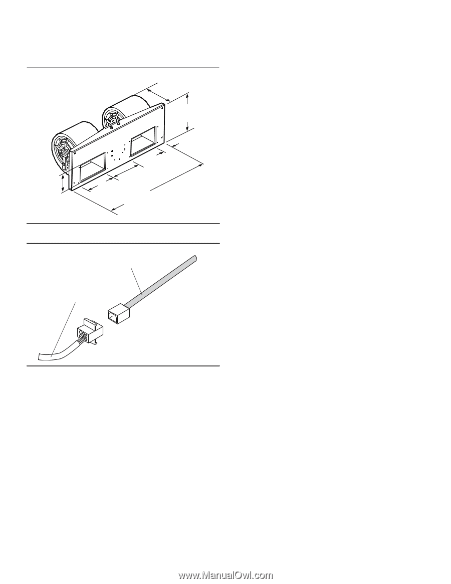
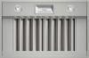
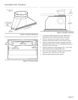
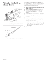
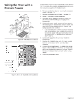
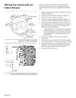
Wiring the Hood with an Integral Blower 81/4" (210 mm) 87/8" (225 mm) 41/8" (105 mm) 21/4" (57 mm) 63/4" 67/8" (171 mm) (175 mm) 25" (635 mm) Figure 6: Integral Blower Model VTN1030C From Blower Integral Blower models VTN630C and VTN1030C are integrated into the hood at the time of installation (VCIN models). For complete installation instructions see the instructions supplied with the blower unit. 1. Remove junction box channel covering the wires (see Figure 5 on page 11). 2. Remove circular knockouts (Figure 5 on page 11). 3. Connect the blower's Molex plug connector to the connector present inside the hood, as shown in Figure 7. 4. Install 1" (25.4 mm) conduit connector in junction box. 5. Run black, white, and green wires (#12 AWG) in 1" (25.4 mm) conduit from the power supply to the junction box. 6. Connect the power supply wires to the hood wires in the following order: black to black, white to white, and green wire to green ground screw on chassis. Use spring type wire nuts supplied. • Lost or missing wire nuts should only be replaced with spring type wire nuts rated for a minimum of two (2) #18 gauge wires and maximum of four (4) #14 gauge wires, UL & CSA rated to 600V and 302°F (150°C.) 7. Close the junction box cover. From Control Panel Figure 7: Wiring the Hood with an Integral Blower English 12
-
 1
1 -
2
-
3
-
4
-
5
-
6
-
7
-
8
-
 9
9 -
 10
10 -
 11
11 -
 12
12 -
 13
13 -
 14
14 -
 15
15 -
 16
16 -
 17
17 -
 18
18 -
 19
19 -
20
-
21
-
22
-
23
-
24
-
25
-
26
-
27
-
28
-
29
-
30
-
31
-
32
-
33
-
34
-
35
-
36
-
37
-
38
-
39
-
40
-
41
-
42
-
43
-
44
-
45
-
46
-
47
-
48
-
49
-
50
-
51
-
52
-
53
-
54
-
55
-
56
-
57
-
58
-
59
-
60
-
61
-
62
-
63
-
64
-
65
-
66
-
67
-
68
-
69
-
70
-
71
-
72
-
73
-
74
-
75
-
76
-
77
-
78
-
79
-
80
-
81
-
82
-
83
-
84
-
85
-
86
-
87
-
88
-
89
-
90
-
91
-
92
-
93
-
94
-
95
-
96
 |
 |