Thermador VCIN36JP Installation Instructions - Page 18
Prepare wall or similar surface for installation as shown below
 |
View all Thermador VCIN36JP manuals
Add to My Manuals
Save this manual to your list of manuals |
Page 18 highlights
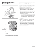
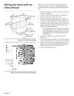
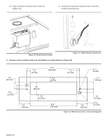
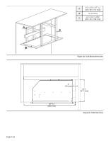
d) Plug in harness included in the remote kit (Figure 16). e) Connect the extension harness to the connector inside the junction box. Figure 16: Relay Board Hookup Figure 17: Pigtail Remote Connection 3. Prepare wall or similar surface for installation as shown below in Figure 18. 1½" (40 mm) 15/16" (23 mm) 11/16" (17 mm) 2¾" (69 mm) 11¾" (298 mm) 3/16" (5 mm) 11/16" (17 mm) ¼" (6 mm) 1½" (40 mm) 1 3/8" (35 mm) 3/8" (10 mm) 10 3/8" (263 mm) 1 3/8" (35 mm) 5/8" (17 mm) 9/16" (15 mm) Figure 18: Wall Cutout (view is shown facing wall) English 16
-
 1
1 -
2
-
3
-
4
-
5
-
6
-
7
-
8
-
9
-
10
-
11
-
12
-
 13
13 -
 14
14 -
 15
15 -
 16
16 -
 17
17 -
 18
18 -
 19
19 -
 20
20 -
 21
21 -
 22
22 -
 23
23 -
24
-
25
-
26
-
27
-
28
-
29
-
30
-
31
-
32
-
33
-
34
-
35
-
36
-
37
-
38
-
39
-
40
-
41
-
42
-
43
-
44
-
45
-
46
-
47
-
48
-
49
-
50
-
51
-
52
-
53
-
54
-
55
-
56
-
57
-
58
-
59
-
60
-
61
-
62
-
63
-
64
-
65
-
66
-
67
-
68
-
69
-
70
-
71
-
72
-
73
-
74
-
75
-
76
-
77
-
78
-
79
-
80
-
81
-
82
-
83
-
84
-
85
-
86
-
87
-
88
-
89
-
90
-
91
-
92
-
93
-
94
-
95
-
96
 |
 |
English 16
d)
Plug in harness included in the remote kit
(
Figure 16
).
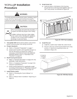
e)
Connect the extension harness to the connector
inside the junction box.
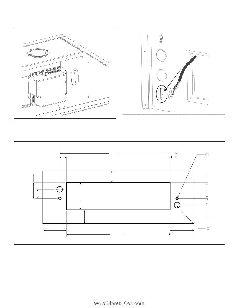
3.
Prepare wall or similar surface for installation as shown below in
Figure 18
.
Figure 16: Relay Board Hookup
Figure 17: Pigtail Remote Connection
Figure 18: Wall Cutout (view is shown facing wall)
11¾”
(298 mm)
11
/
16
”
(17 mm)
¼”
(6 mm)
1½”
(40 mm)
(17 mm)
(15 mm)
9
/
16
”
5
/
8
”
1½”
(40 mm)
10
(263 mm)
3
/
8
”
11
/
16
”
(17 mm)
2¾”
(69 mm)
(23 mm)
15
/
16
”
1
(35 mm)
3
/
8
”
1
(35 mm)
3
/
8
”
(10 mm)
3
/
8
”
(5 mm)
3
/
16
”