Thermador VCIN36JP Installation Instructions - Page 13
Installation Instructions
 |
View all Thermador VCIN36JP manuals
Add to My Manuals
Save this manual to your list of manuals |
Page 13 highlights
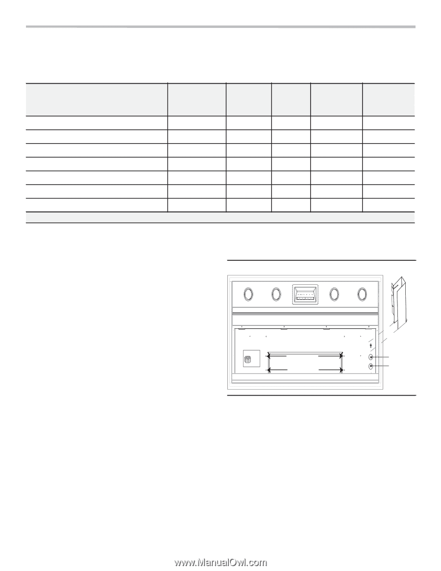
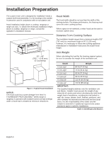
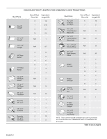
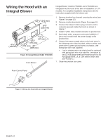
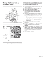
Installation Instructions Blower Motor Installation BLOWER Integral Blower 600 CFM Integral Blower 1000 CFM Remote Blower 600 CFM Remote Blower 1000 CFM Remote Blower 1300 CFM Inline Blower 600 CFM Inline Blower 1000 CFM * CFM= Cubic feet per minute SKU VTN630C VTN1030C VTR630D VTR1030D VTR1330E VTI610D VTI1010D Integral blower installation only 1. The blower is attached to the hood using weld studs provided on the mounting plate. Figure 5 exhibits the weld stud locations. 2. Guide the motor mounting plate over the studs. 3. Attach four (4) nuts (included with hood) to the weld studs. Tighten nuts to secure the blower to the hood. 4. Continue to "Wiring the Hood with an Integral Blower" on page 12. CFM* 600 1000 600 1000 1300 600 1000 VOLTAGE (AC) BLOWER CURRENT (AMPS) 120 2.7 120 5.4 120 4.2 120 5.7 120 8.5 120 4.2 120 5.7 CIRCUIT BREAKER (AMPS) 15 15 15 15 15 15 15 Table 5: Blower & Circuit Breaker Ratings x4 Weld Studs Knockouts behind junction box Figure 5: Weld Stud & Junction Box Locations English 11
-
 1
1 -
2
-
3
-
4
-
5
-
6
-
7
-
 8
8 -
 9
9 -
 10
10 -
 11
11 -
 12
12 -
 13
13 -
 14
14 -
 15
15 -
 16
16 -
 17
17 -
 18
18 -
19
-
20
-
21
-
22
-
23
-
24
-
25
-
26
-
27
-
28
-
29
-
30
-
31
-
32
-
33
-
34
-
35
-
36
-
37
-
38
-
39
-
40
-
41
-
42
-
43
-
44
-
45
-
46
-
47
-
48
-
49
-
50
-
51
-
52
-
53
-
54
-
55
-
56
-
57
-
58
-
59
-
60
-
61
-
62
-
63
-
64
-
65
-
66
-
67
-
68
-
69
-
70
-
71
-
72
-
73
-
74
-
75
-
76
-
77
-
78
-
79
-
80
-
81
-
82
-
83
-
84
-
85
-
86
-
87
-
88
-
89
-
90
-
91
-
92
-
93
-
94
-
95
-
96
 |
 |