Thermador VCIN36JP Installation Instructions - Page 16
Wiring the Hood with an, Inline Blower
 |
View all Thermador VCIN36JP manuals
Add to My Manuals
Save this manual to your list of manuals |
Page 16 highlights
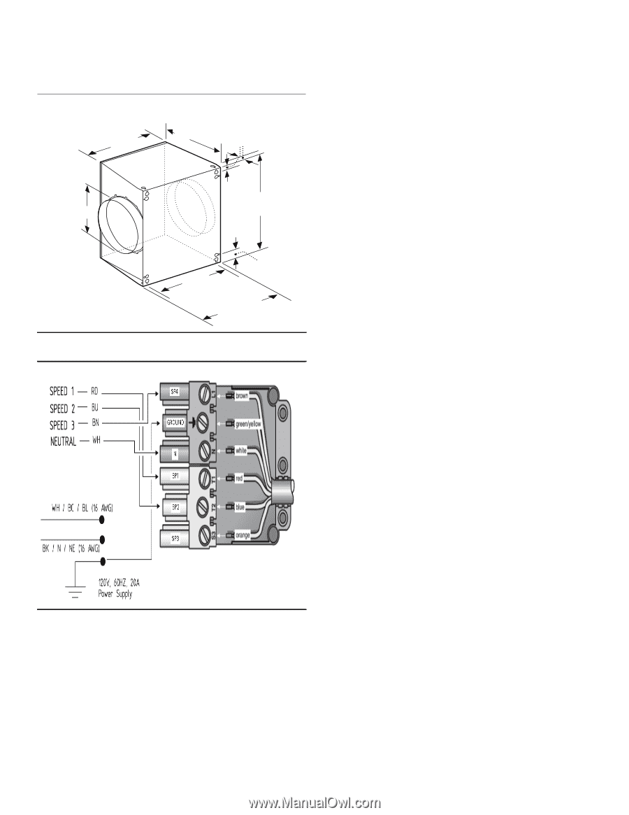
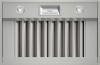
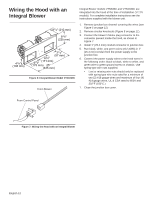
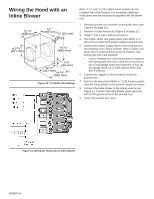
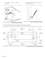
Wiring the Hood with an Inline Blower Both VCIN and VCIB custom insert models can be installed with inline blowers. For complete installation instructions see the instructions supplied with the blower unit. 12 1/8" (308 mm) 12 " (305 mm) 7/8" (22 mm) ø 9 7/8" (251 mm) 19 1/8" (486 mm) 13/4" (44 mm) 12 7/8" (327 mm) 14 3/8" (365 mm) Figure 10: VTI1010D Inline Blower 1. Remove junction box channel covering the wires (see Figure 5 on page 11). 2. Remove circular knockouts (Figure 5 on page 11). 3. Install 1" (25.4 mm) conduit connectors. 4. Run black, white, and green wires (#12 AWG) in 1" (25.4 mm) conduit from power supply to junction box. 5. Connect the power supply wires to the hood wires in the following order: black to black, white to white, and green wire to green ground screw on chassis. Use spring type wire nuts supplied. • Lost or missing wire nuts should only be replaced with spring type wire nuts, rated for a minimum of two (2 #18 gauge wires and maximum of four (4) #14 gauge wires, UL & CSA rated to 600V and 302°F (150°C). 6. Connect the "pigtail" to the connector inside the junction box. 7. Run five (5) wires (#14 AWG) in 1" (25.4 mm) conduit from the inline blower to the second conduit connector. 8. Connect the inline blower to the pigtail wires as per Figure 11. Connect the inline blower green (ground) wire to the ground screw in the junction box. 9. Close the junction box cover. Figure 11: Wiring the Hood with an Inline Blower English 14
-
 1
1 -
2
-
3
-
4
-
5
-
6
-
7
-
8
-
9
-
10
-
 11
11 -
 12
12 -
 13
13 -
 14
14 -
 15
15 -
 16
16 -
 17
17 -
 18
18 -
 19
19 -
 20
20 -
 21
21 -
22
-
23
-
24
-
25
-
26
-
27
-
28
-
29
-
30
-
31
-
32
-
33
-
34
-
35
-
36
-
37
-
38
-
39
-
40
-
41
-
42
-
43
-
44
-
45
-
46
-
47
-
48
-
49
-
50
-
51
-
52
-
53
-
54
-
55
-
56
-
57
-
58
-
59
-
60
-
61
-
62
-
63
-
64
-
65
-
66
-
67
-
68
-
69
-
70
-
71
-
72
-
73
-
74
-
75
-
76
-
77
-
78
-
79
-
80
-
81
-
82
-
83
-
84
-
85
-
86
-
87
-
88
-
89
-
90
-
91
-
92
-
93
-
94
-
95
-
96
 |
 |