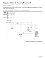
Thermador VCIN36JP Installation Instructions - Page 24
on, on Refer to Installing Grease Trays,
 |
View all Thermador VCIN36JP manuals
Add to My Manuals
Save this manual to your list of manuals |
Page 24 highlights
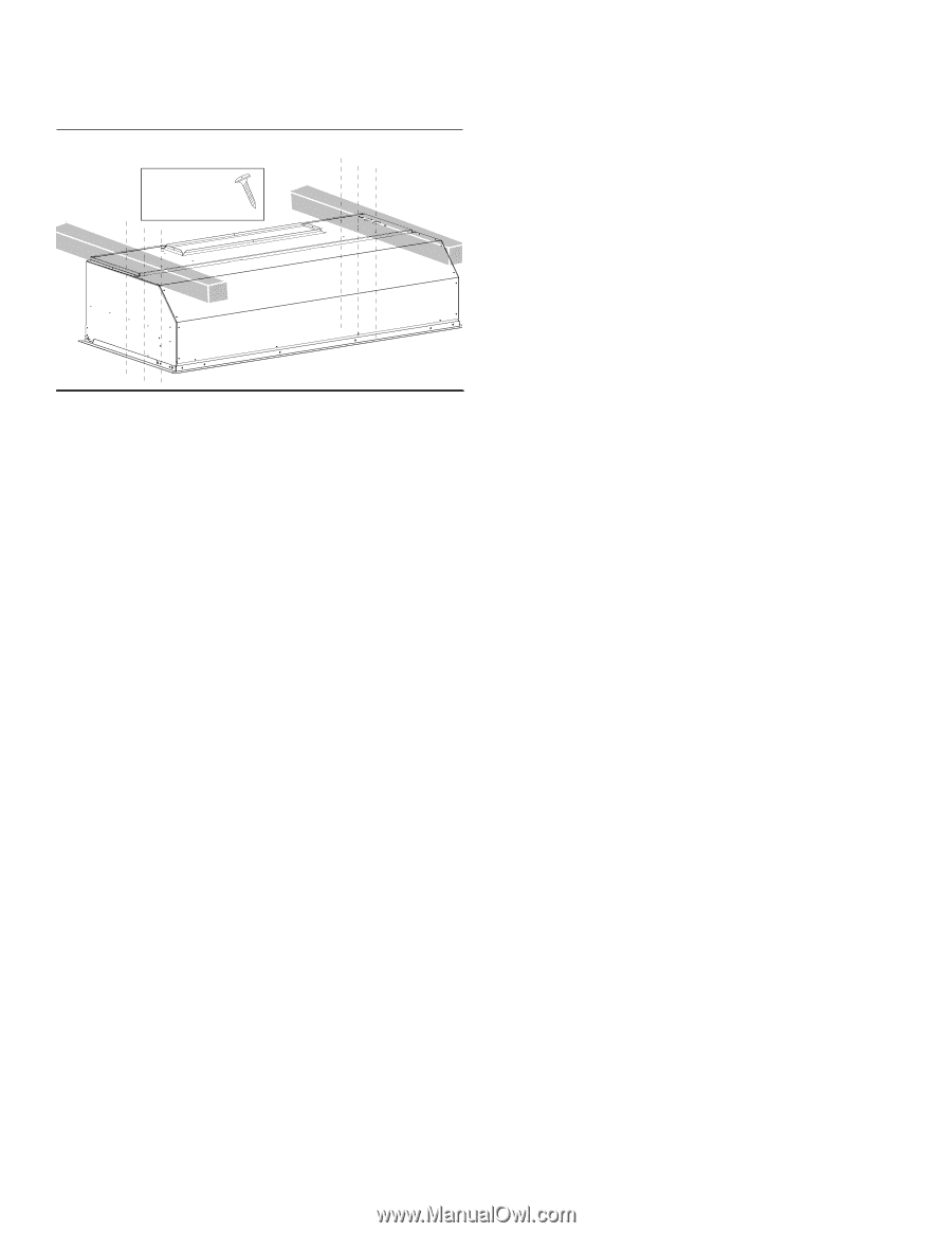
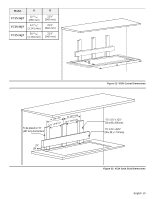
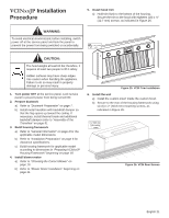
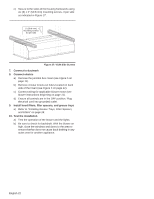
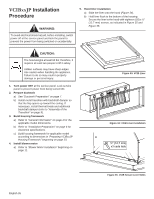
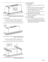
c) Secure to the sides of the housing framework using six (6) x 2" (50.8 mm) mounting screws, 3 per side as indicated in Figure 27. 2" (50.8 mm) mounting screws X3 per side Figure 27: VCIN Side Screws 7. Connect to ductwork 8. Connect electric a) Remove the junction box cover (see Figure 5 on page 11). b) Remove circular knock-out holes located on back side of the insert (see Figure 5 on page 11). c) Connect wiring for applicable blower motor (see blower instructions beginning on page 11). d) Ensure all controls are in the OFF position. Plug electrical cord into grounded outlet. 9. Install hood filters, filter spacers, and grease trays a) Refer to "Installing Grease Trays, Filter Spacers, and Filters" on page 28. 10. Test the installation a) Test the operation of the blower and the lights. b) Be sure to check for backdraft. With the blower on high, close the windows and doors to the area to ensure that fan does not cause back drafting in any outlet vent for another appliance. English 22
-
 1
1 -
2
-
3
-
4
-
5
-
6
-
7
-
8
-
9
-
10
-
11
-
12
-
13
-
14
-
15
-
16
-
17
-
18
-
 19
19 -
 20
20 -
 21
21 -
 22
22 -
 23
23 -
 24
24 -
 25
25 -
 26
26 -
 27
27 -
 28
28 -
 29
29 -
30
-
31
-
32
-
33
-
34
-
35
-
36
-
37
-
38
-
39
-
40
-
41
-
42
-
43
-
44
-
45
-
46
-
47
-
48
-
49
-
50
-
51
-
52
-
53
-
54
-
55
-
56
-
57
-
58
-
59
-
60
-
61
-
62
-
63
-
64
-
65
-
66
-
67
-
68
-
69
-
70
-
71
-
72
-
73
-
74
-
75
-
76
-
77
-
78
-
79
-
80
-
81
-
82
-
83
-
84
-
85
-
86
-
87
-
88
-
89
-
90
-
91
-
92
-
93
-
94
-
95
-
96
 |
 |