Troy-Bilt Pro-Line CRT Service Manual - Page 12
Cut A Way for Spiral Pin,
 |
View all Troy-Bilt Pro-Line CRT manuals
Add to My Manuals
Save this manual to your list of manuals |
Page 12 highlights
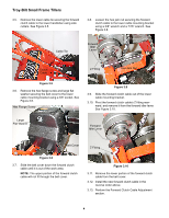
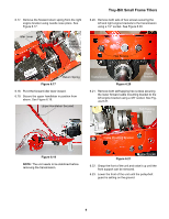
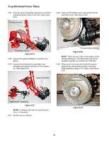
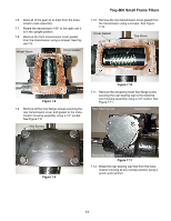
Troy-Bilt Small Frame Tillers 6.12. Remove the depth regulator assembly and drag bar assembly. See Figure 6.12. Depth Regulator Assembly 6.14. Raise the front of the tiller up until the wheel assemblies are off the ground. See Figure 6.14. Hood Brackets Drag Bar Figure 6.12 NOTE: There is a cut a way in the tine hood to allow the depth bar's spiral pin to pass through. See Image Below. Cut A Way Wheels off Ground Raise the Unit Up Figure 6.14 6.15. Remove both hair pins and clevis pins securing the wheel assemblies onto the wheel shaft using needle nose pliers. See Figure 6.15. Cut A Way for Spiral Pin 6.13. Lower the unit back onto the tines. NOTE: Make certain the unit is resting on the tines and not on the trailing shield. Hair Pin Clevis Pin Figure 6.15 6.16. Remove both wheel assemblies. 8
-
 1
1 -
2
-
3
-
4
-
5
-
6
-
 7
7 -
 8
8 -
 9
9 -
 10
10 -
 11
11 -
 12
12 -
 13
13 -
 14
14 -
 15
15 -
 16
16 -
 17
17 -
18
-
19
-
20
-
21
-
22
-
23
-
24
-
25
-
26
-
27
-
28
-
29
-
30
-
31
-
32
-
33
-
34
-
35
-
36
-
37
-
38
-
39
-
40
-
41
-
42
 |
 |
