Troy-Bilt Pro-Line CRT Service Manual - Page 30
Troy-Bilt Pro-Line CRT Manual
 |
View all Troy-Bilt Pro-Line CRT manuals
Add to My Manuals
Save this manual to your list of manuals |
Page 30 highlights
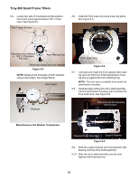
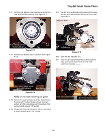
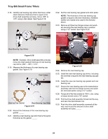
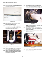
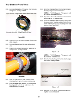
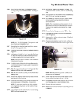
Troy-Bilt Small Frame Tillers 8.35. Drive the Hi-Pro key into the wheel shaft using a soft mallet. See Figure 8.35. 8.41. Drive the second wheel shaft bronze bushing into the transmission housing until it is flush with the outside of the housing using a bushing driver and hammer. See Figure 8.41. Hi-Pro Key Wheel Shaft Figure 8.35 8.36. Lubricate the I.D. of the wheel shaft bronze bushing that has been installed. 8.37. Slowly install the drive shaft through the opposite bushing bore, through the wheel shaft worm gear and spacer, and into the installed wheel shaft bronze bushing. See Figure 8.37. Drive Shaft Wheel Shaft Worm Gear Bronze Bushing Bronze Bushing Flush With Housing Figure 8.41 NOTE: A 1" I.D. PVC pipe by 7" long works well as a bushing installation tool. 8.42. Drive the first wheel shaft bronze bushing into the transmission housing until it is flush with the outside of the housing. 8.43. Position a dial indicator at one end of the wheel shaft. See Figure 8.43. Magnetic Stand Spacer Spacer Figure 8.37 8.38. Slide the Hi-Pro key into the wheel shaft worm gear. 8.39. Slide the second spacer over the wheel shaft until it contacts the wheel shaft worm gear. 8.40. Slide the second wheel shaft bronze bushing over the drive shaft, making certain the lubrication cut a ways are facing in. Pull Shaft Out Dial Indicator Figure 8.43 8.44. Pull the wheel shaft all the way to one side and zero in the dial indicator. 26
-
 1
1 -
2
-
3
-
4
-
5
-
6
-
7
-
8
-
9
-
10
-
11
-
12
-
13
-
14
-
15
-
16
-
17
-
18
-
19
-
20
-
21
-
22
-
23
-
24
-
 25
25 -
 26
26 -
 27
27 -
 28
28 -
 29
29 -
 30
30 -
 31
31 -
 32
32 -
 33
33 -
 34
34 -
 35
35 -
36
-
37
-
38
-
39
-
40
-
41
-
42
 |
 |
