Viking VUWC Installation Instructions - Page 6
Anti-Tip Bracket
 |
View all Viking VUWC manuals
Add to My Manuals
Save this manual to your list of manuals |
Page 6 highlights
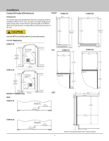
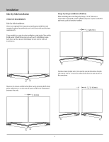
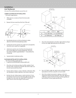
Installation Anti-Tip Bracket Use one of the methods below to secure the unit CABINET/COUNTER ANTI-TIP INSTALLATION (For built-in applications) 1. Slide unit out so screws on front of unit are easily accessible. 2. Remove the two screws from the front of the unit. 3. Bend bracket along one of the perforations to allow attachment to the desired adjoining surface. 4. Gently push unit into position. Be careful not to entangle the electrical cord or water line, if applicable. 5. Check to be sure the unit is level from front to back and side to side. Make any necessary adjustments. The unit's top surface should be approximately 1⁄8" (3 mm) below the countertop. 6. Secure bracket to adjoining surface. FLOOR MOUNTED ANTI-TIP INSTALLATION (For free-standing applications) 1. Locate two anti-tip brackets included with the kit. 2. Place the unit into the area where it will be installed. Check the door, sides, and top for a proper fit. Also test to make sure the door opens and closes freely. 3. Remove grille and place a mark on the floor at the front of the unit. Also place a mark on the floor in the center of the unit. 4. Remove the unit. Using a square, extend center line "B" (see chart below). This line serves as the back edge for the anti-tip brackets. From the center line, measure "A" to the left and right. This line is the outer edge of each bracket. Surrounding area (Top view) Back of unit Back wall B A CL A 515 Front of unit 524 A 7 5⁄8" (194 mm) 11 15⁄16" (303 mm) B 22" (558 mm) 22" (558 mm) 5. Place the anti-tip brackets on the floor against the line drawn for the outer edge. Mark spots for the screw holes. Surrounding area (Top view) Drill holes and mount anti-tip brackets to floor Back wall Front of unit A CL B A Back of unit 6. Use a 1/8" drill to make two starter holes and fasten the antitip brackets to the floor using the screws provided. 7. Place the unit back into position, making sure the feet engage the anti-tip brackets properly. Check the alignment of the lines made on the floor in step 3 with the position of the front feet to ensure proper positioning. 6
-
 1
1 -
 2
2 -
 3
3 -
 4
4 -
 5
5 -
 6
6 -
 7
7 -
 8
8 -
 9
9 -
 10
10 -
 11
11 -
 12
12 -
13
-
14
-
15
-
16
-
17
-
18
-
19
-
20
-
21
-
22
-
23
-
24
-
25
-
26
-
27
-
28
-
29
-
30
-
31
-
32
-
33
-
34
-
35
-
36
-
37
-
38
-
39
-
40
-
41
-
42
-
43
-
44
-
45
-
46
-
47
-
48
-
49
-
50
-
51
-
52
-
53
-
54
-
55
-
56
-
57
-
58
-
59
-
60
 |
 |
